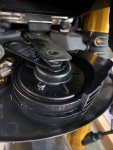
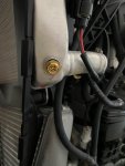
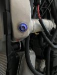
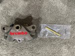
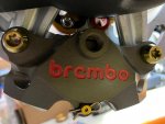
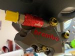
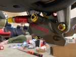
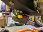
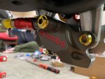
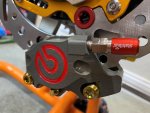
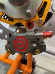
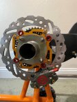
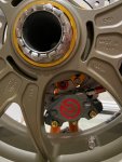
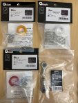
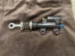
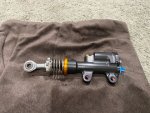
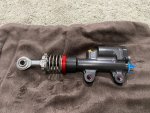
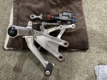
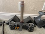
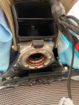
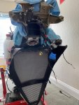
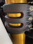
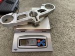
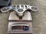
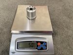
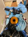
The 3D printed bracket for the ChaseBay F Brake Line Distributor, that I post a few pages back was just the FIRST prototype and it won't work because it did not have enough space to accommodate the -3AN Brake Line NUT.
Today, I also want to check the holes (diameter and spacing) to secure it to the lower triple clamp, and as I suspect, it also don't work well.
This is NORMAL since this is just the FIRST prototype. I mentioned that this is just a NON WORKING Prototype/Design long time ago at the old forum.
However, it doesn't help when a "NON-technical savvy character", who never read the details (and like to be spoon feed) start demanding to get the CAD files of this design so he can use it on his bike.
Heck, it wasn't even a working prototype
This created a drama at the old forum that looking back, is actually a blessing in disguise.
Because that drama motivated me (with the support of many FOUNDING Members of this forum) to create this NEW Forum that can provide a COMFORTABLE place for any poster (especially the CONTENT Contributor/Provider or VENDOR) !
So, before anyone start asking for the CAD files again, let me put a disclosure, once and for all, that the CAD files is NOT for sale and I will NOT give it out to anyone.
This is related to braking system, and it's a LEGAL LIABILITY for me.
Having said that, just by looking at my pictures, it will be very easy for any reader to take some measurement and copy my design. (or better, IMPROVE on my crude design). Just have to be willing to do a thing call measuring
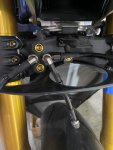
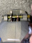
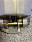
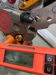
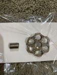
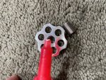
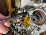
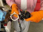
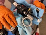
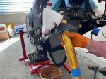
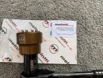
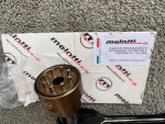
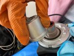
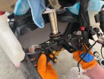
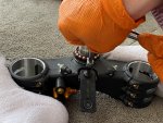
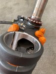
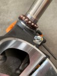
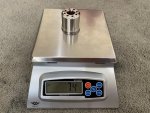
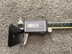
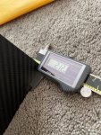
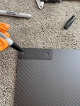
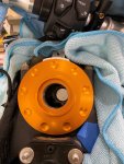
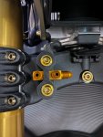
Here is the old design being tested today with the 35mm long ProTi M5 Titanium bolt, and turn out the hole diameter is too small, making it hard (and could damage the thread) to thread it onto the lower triple clamp:
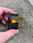
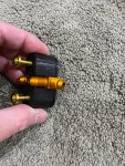
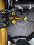
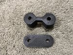
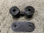
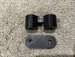
So based on the testing above, I asked my younger son to make several adjustments to the design, listed below:
a. Make the hole diameter for the bolts to 6mm to allow some slack making it easy to thread and allow easy threading into the lower triple clamp
b. Cut a 45 degree angle corner to give more space for the -3AN brake line nut
c. Make the center part thinner my 1 mm again to give more space for the -3AN brake line nut
d. Make the BASEPLATE thicker from 3mm to 5mm for a more stable base
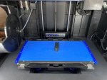
My younger son quickly work on his computer and in just 10 minutes, his 3D Printer already start printing again
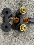
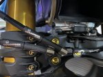
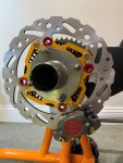
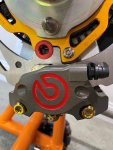
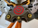
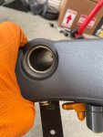
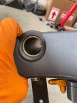
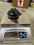
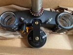
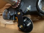
and here are the pictures of the SECOND Prototype:
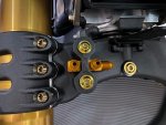
Hopefully this SECOND Prototype will be the Final revision... and I should know this by next weekend when I screw in the -3AN nut from Goodridge to make sure the spacing is really enough.
If everything goes ok, then... I will have a CNC Machine Shop make it out of 7075-T3 Aluminum or hmmm maybe even Titanium if the price is right (meaning still affordable)
Today, I also want to check the holes (diameter and spacing) to secure it to the lower triple clamp, and as I suspect, it also don't work well.
This is NORMAL since this is just the FIRST prototype. I mentioned that this is just a NON WORKING Prototype/Design long time ago at the old forum.
However, it doesn't help when a "NON-technical savvy character", who never read the details (and like to be spoon feed) start demanding to get the CAD files of this design so he can use it on his bike.
Heck, it wasn't even a working prototype
This created a drama at the old forum that looking back, is actually a blessing in disguise.
Because that drama motivated me (with the support of many FOUNDING Members of this forum) to create this NEW Forum that can provide a COMFORTABLE place for any poster (especially the CONTENT Contributor/Provider or VENDOR) !
So, before anyone start asking for the CAD files again, let me put a disclosure, once and for all, that the CAD files is NOT for sale and I will NOT give it out to anyone.
This is related to braking system, and it's a LEGAL LIABILITY for me.
Having said that, just by looking at my pictures, it will be very easy for any reader to take some measurement and copy my design. (or better, IMPROVE on my crude design). Just have to be willing to do a thing call measuring
Here is the old design being tested today with the 35mm long ProTi M5 Titanium bolt, and turn out the hole diameter is too small, making it hard (and could damage the thread) to thread it onto the lower triple clamp:


So based on the testing above, I asked my younger son to make several adjustments to the design, listed below:
a. Make the hole diameter for the bolts to 6mm to allow some slack making it easy to thread and allow easy threading into the lower triple clamp
b. Cut a 45 degree angle corner to give more space for the -3AN brake line nut
c. Make the center part thinner my 1 mm again to give more space for the -3AN brake line nut
d. Make the BASEPLATE thicker from 3mm to 5mm for a more stable base
My younger son quickly work on his computer and in just 10 minutes, his 3D Printer already start printing again
and here are the pictures of the SECOND Prototype:


Hopefully this SECOND Prototype will be the Final revision... and I should know this by next weekend when I screw in the -3AN nut from Goodridge to make sure the spacing is really enough.
If everything goes ok, then... I will have a CNC Machine Shop make it out of 7075-T3 Aluminum or hmmm maybe even Titanium if the price is right (meaning still affordable)

