DUCATI Panigale V4 25° Anniversario 916 BUILD Thread

POMPLARDPANAM

Active member
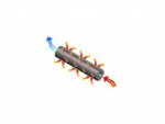
I really don't think that Ducabike hose will help much. As Howard said, it is designed for the streetfighter. Fairings will direct air that has already passed through the radiator over the hose, meaning it is already heat-saturated air. The surface area on a bit of hose is nothing compared to that on the radiator. It's just a flashy bit for streetfighters that doesn't do much in the first place, really is no reason to apply it to a Panigale.
Yeah but i wanna try it my bro...it will help a lil bit or...not

Ducabike hose explaination.jpg
 

BMW Alpina

FOUNDING Member & Administrator
Staff member
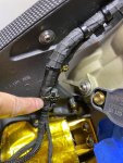
So, my goal this long weekend was to finish with running (securing) the wiring to the rear ABS sensor along the cooper solid like that goes to the rear brake, however, that means it will involve several steps including fixing the position of the large SC-Project WSBK exhaust pipe near the swing arm hub,
so I know the exact position where I can locate the wiring as far as possible. I also need to fit the right rear set since the brake light switch wiring is secured together with the rear ABS sensor wiring from the factory. I want to make all the wire secured exactly like the way Ducati factory secured them.

This means, I need to first install all the bracket for the Termignoni silencers that I took out for Cerakote coating, because this will have effect on the position of the exhaust pipe near the swing arm hub.
Before, all the Rizoma brackets and black aluminum spacers have different shades of black anodizing color and somehow it did not look "integrated" enough.

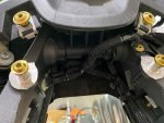
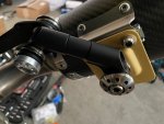
Now all the aluminum parts already coated in the same Cerakote Glacier Black color, including the long bracket for the rear subframe, and this really make a lot of differences where everything is now looks INTEGRATED like it came like that from the factory.;)
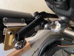
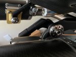
Also, notice how smooth the gold cerakote bracket on the Termignoni silencer too:


IMG_3148.JPGIMG_3166.JPG

IMG_3147.JPGIMG_3151.JPG

By the way, I also "ADJUST" and "TUNE" the black Rizoma mirror bracket above with different spacer length between them since the left and right Termignoni mounting location is assymetrical but you won't notice unless I point it up to you.
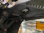
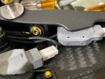
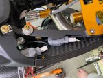
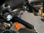
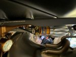
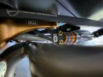
I also "ADJUST" and "TUNE" the silencer position so it push the "Y" pipe away from the Ohlins Rear Shock Pre-Load Adjuster HYDRAULIC HOSE as far as possible. Eventhough I already use the Goodridge Heat Protecting sleeve, but I still want it to have "space" between them.
and here are the current space available:
IMG_3179.JPGIMG_3180.JPG

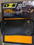
But, I also had prepared an EXTRA safety measure using DEI Heat Protection Fabric:
IMG_3141.JPG

I will install this before I took the bike to the dealership for the UPMAP install because I worry they might need to run the engine for a while and the exhaust pipe will be hot...
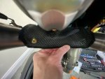
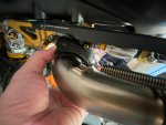
Test fit the DEI Flexible Heat Shield fabric: and they fit like a glove (y)
IMG_3143.JPGIMG_3142.JPG

Of course, per DUCATImodified standard, even the Fabric HeatShield need to be upgraded with ProTi Titanium Bolt, so I am ordering more ProTibolts, but in the meantime, just one bolt for test fit:
IMG_3140.JPG

More update soon 😎
 

POMPLARDPANAM

Active member
So, my goal this long weekend was to finish with running (securing) the wiring to the rear ABS sensor along the cooper solid like that goes to the rear brake, however, that means it will involve several steps including fixing the position of the large SC-Project WSBK exhaust pipe near the swing arm hub,
so I know the exact position where I can locate the wiring as far as possible. I also need to fit the right rear set since the brake light switch wiring is secured together with the rear ABS sensor wiring from the factory. I want to make all the wire secured exactly like the way Ducati factory secured them.

This means, I need to first install all the bracket for the Termignoni silencers that I took out for Cerakote coating, because this will have effect on the position of the exhaust pipe near the swing arm hub.
Before, all the Rizoma brackets and black aluminum spacers have different shades of black anodizing color and somehow it did not look "integrated" enough.

Now all the aluminum parts already coated in the same Cerakote Glacier Black color, including the long bracket for the rear subframe, and this really make a lot of differences where everything is now looks INTEGRATED like it came like that from the factory.;)
Also, notice how smooth the gold cerakote bracket on the Termignoni silencer too:


View attachment 5550View attachment 5553

View attachment 5552View attachment 5551

By the way, I also "ADJUST" and "TUNE" the black Rizoma mirror bracket above with different spacer length between them since the left and right Termignoni mounting location is assymetrical but you won't notice unless I point it up to you.
I also "ADJUST" and "TUNE" the silencer position so it push the "Y" pipe away from the Ohlins Rear Shock Pre-Load Adjuster HYDRAULIC HOSE as far as possible. Eventhough I already use the Goodridge Heat Protecting sleeve, but I still want it to have "space" between them.
and here are the current space available:
View attachment 5554View attachment 5555

But, I also had prepared an EXTRA safety measure using DEI Heat Protection Fabric:
View attachment 5556

I will install this before I took the bike to the dealership for the UPMAP install because I worry they might need to run the engine for a while and the exhaust pipe will be hot...
Test fit the DEI Flexible Heat Shield fabric: and they fit like a glove (y)
View attachment 5557View attachment 5559

Of course, per DUCATImodified standard, even the Fabric HeatShield need to be upgraded with ProTi Titanium Bolt, so I am ordering more ProTibolts, but in the meantime, just one bolt for test fit:
View attachment 5558

More update soon 😎
Nice i need something like that too
 

POMPLARDPANAM

Active member
Hello POMPLARDPANAM,

Good to hear from you. I hope the dealership can fix your oil pan thread screw soon so you can ride your bike again.

First, I don't think the DucaBike will help much with releasing heat because first, their heat sink fin area is not that great, and second it will be hidden from air flow behind our fairing (unlike Streetfighter) so it will NOT be able to release much heat onto the moving air.

Second, when you buy the Samco Hoses, make sure you order from:
Bruce Hatton who is the MAIN Distributor for Samco Hoses for motorcycle application. He is the one who replace my Samco hose with the correct length for FREE eventhough I purchase from Demon Tweeks UK.
Bruce and his company RaceBike Bitz is the GLOBAL distributor of Samco hose for Motorcycle application and here is his email:
Bruce.Hatton at racebikebitz.com
Mention that you are member of Ducatimodified.com because Bruce told me he will give our member a discount.

View attachment 5538
Hi thanks again bro i have just send a mail to this guy Bruce HATTON N his team to negociate a price with it's like that without the discount :unsure: 🧐:unsure: https://racebikebitz.com/index.php?route=checkout/cart
Red is out of stock...
i will see what to do the prices on e- bay R good too + on e-bay i can negociate sometimes too
 

BMW Alpina

FOUNDING Member & Administrator
Staff member
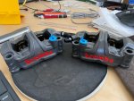
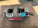
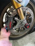
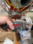
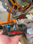
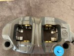
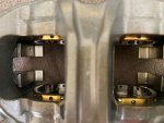
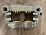
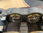
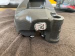
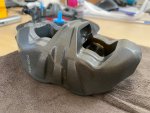
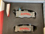
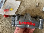
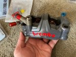
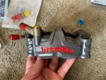
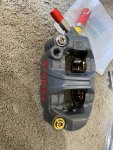
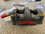
So today is a day that I had been waiting for because I supposed to received my Brembo GP4-RR calipers that I had been waiting since August, and UPS did deliver it today.
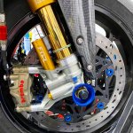
However, when I open the package, I am so surprised that the GP4-RR calipers that I received had a DARK GREY color because from what I see everywhere on the internet, the color is supposed to be GOLD Color.

Here are the pictures:
IMG_3254.JPG IMG_3256.JPG

IMG_3250.JPGIMG_3253.JPG

I compare it with my rear billet Brembo caliper:
IMG_3249.JPGIMG_3251.JPG

More pictures:
IMG_3257.JPGIMG_3258.JPG

IMG_3259.JPGIMG_3260.JPG

IMG_3261.JPGIMG_3262.JPG

IMG_3263.JPG

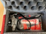
It could be the way the lighting on all the other pictures play some affect because here is another picture inside the box where it looks a bit gold:
IMG_3247.JPG

However, this is really weird. I am checking with Bellissimoto and also directly with Brembo (Race Technologies) to clarify...

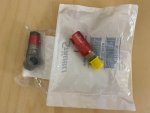
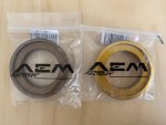
By the way other parts also arrive like 1 set of Staubli for this Front caliper test fitting, some more AEM Factory rear wheel spacer to complete my color collections of this spacer and also the RCS19 Corsa Corta MC since my RCS17 Corsa Corta is NOT designed for the GP4-RR larger Piston:
IMG_3240.JPGIMG_3241.JPG
IMG_3246.JPGIMG_3245.JPG

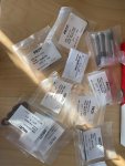
and of course more ProTi:
IMG_3266.JPG

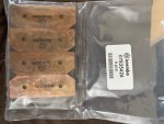
and the Z04 Brake Pads for the GP4-RR:
IMG_3265.JPG
 

HKMP7

First 9 & Moderator
Staff member
Congrats those calipers look amazing! Those titanium pistons are magnificent. One thing with Brembo their colors can be a bit inconsistent based on batches.
 

BMW Alpina

FOUNDING Member & Administrator
Staff member
Congrats those calipers look amazing! Those titanium pistons are magnificent. One thing with Brembo their colors can be a bit inconsistent based on batches.
Thanks HKMP7,
You might be right regarding the color inconsistencies, ...
If this turn out to be inconsistencies in production, then... I might have to paint them and make them look exactly the way I want them to be...
 

BMW Alpina

FOUNDING Member & Administrator
Staff member
I was tired and busy but I managed to do a bit and here is the late last weekend update 😁:

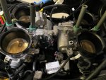
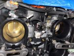
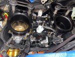
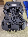
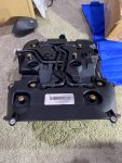
The single ProTi replacement bolt (that I cross threaded last month) finally arrived, so I am able to continue installing the throttle body and the airbox.

Left picture show the temporary stainless steel bolt, and the right picture show the replacement ProTi bolt:
1632191063555.pngIMG_3288.JPG


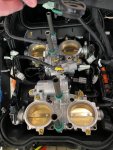
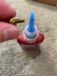
Next place the throttle body assembly on top of the intake manifold, then secure it with ProTi Bolts, don't forget Loctite Medium🧐:
IMG_3289.JPGIMG_3291.JPG

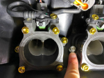
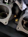
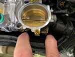
There are 16 bolts that secure the throttle body, yes 16 bolts, and some of the location is quite hard to reach, so be very careful, because if you drop a bolt, it will go below the whole throttle body assembly and you will have to take out the throttle body assembly again to get it...
Also, make sure that the ARROW carved on the Throttle body assy pointing forward because this throttle body is symmetrical so you could accidentally install it 180 degree in the wrong direction.
IMG_3294.JPGIMG_3295.JPG
IMG_3297.JPGIMG_3293.JPG

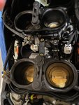
Next, install the LOWER Velocity Stack, of course with ProTi Titanium Bolts and there are total of 8 bolts for the 4 Lower Velocity Stacks:
IMG_3299.JPGIMG_3301.JPG

By the way, I also replace the center connecting bolts that hold the front and rear cylinder together, and that need to be tightened too (pointed by my finger) There are 2 bolts, and I use a SILVER ProTi bolts here since I have some extra silver one:
IMG_3304.JPG

Next, I also tightened the 3 bolts that hold the Variable Height Upper Velocity Stack motor with ProTi Titanium bolts:
IMG_3303.JPG

Oh by the way, all M5 bolts, I tightened to 6.8Nm, the M6 bolts to 10Nm, and M4 to 3Nm, most using Loctite Medium Threadlocker.

Finally, the UPPER Velocity Stack Assembly with the motors is secured with 4 ProTi Titanium Bolts, and I finally can have a sigh or relief because I managed NOT to drop any bolts until the last one installed.
Imagine, if at the last bolt, you drop that bolt, then you have do disassemble this whole throttle body and back from the start again. That would be so exhausting...

IMG_3305.JPGIMG_3308.JPG

IMG_3307.JPG


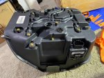
Next, time to install the plug from the SMARTMOTO Secondary Air system Block Off Plate kit since I no longer have secondary air injection system to the hole on the backside of the airbox:
IMG_3309.JPGIMG_3311.JPG

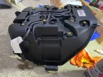
I also replaced all the bolts on top of the airbox itself with ProTi Titanium:
IMG_3312.JPGIMG_3315.JPG

IMG_3313.JPGIMG_3314.JPG

Next is to install the Top Airbox cover and I will update more...
 

BMW Alpina

FOUNDING Member & Administrator
Staff member
A little update for today 😁:

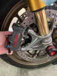
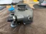
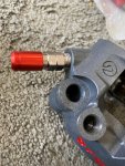
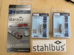
I test fit the Stahlbus quick bleeder because I want to make sure the diameter and the length, and turn out, they are totally different than the stock Stylema caliper both diameter and length.
The GP4-RR require larger diameter but shorter length, so I placed an order for a new pair of Stahlbus quick bleeder valve. Below is the test fit and you can see it is a bit too long, although the diameter is the same as the stock rear brake caliper.
IMG_3278.JPG IMG_3279.JPG

Then I test fit the Staubli dry break, well more like test the color combination... I still think the GP4-RR will look nicer in gold, oh by the way, Brembo USA (Race Technologies) get back to me and they told me the "RACING Dept." caliper anodizing hue will vary and Brembo also under strict "environmental review",
so in summary, this is the color for GP4-RR now.
Well, there is nothing I can do with Brembo anodizing process, but as member of DUCATImodified, I can always "modify" it further... so it will be painted in a different gold color, so stay tune ;)

By the way, why painting, because the Cerakote in gold hue that I like only stable at to 350 Fahrenheit while a high temp paint can be stable at higher temperature than that, so I will go with paint this time.

more pictures during test fit with the Staubli and I also play with different combination of ProTi Titanium Banjo Bolts color:
IMG_3280.JPGIMG_3282.JPG

and of course the color of the bolt that secure the brake caliper to the bracket it self:
IMG_3284.JPGIMG_3286.JPG
 

BMW Alpina

FOUNDING Member & Administrator
Staff member
Little update on the weekend 😁,
I was busy with fixing my backyard sprinkler system and taking my puppy to the vet on Saturday, so I only have a bit of time on Sunday which I used to install the ECU and other wiring near the airbox:

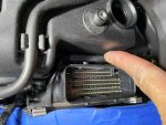
First slide the ECU rubber jacket onto the top and bottom slots located on the airbox, it is very important to make sure the rubber jacket slot properly since this is the only mounting area which bear the weight of the ECU:
IMG_3341.JPG IMG_3343.JPG

Next, plug in the socket onto the ECU:
IMG_3344.JPG

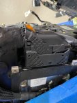
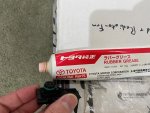
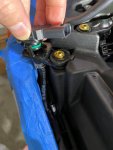
Then install the MAP sensor (front side), and to make sure the O-Ring is properly sealing the holes, I add some Toyota rubber grease to help the insertion process:
IMG_3345.JPG

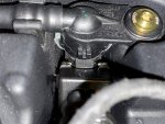
Oh, as you can see on the picture below I already replace the bolt holding the MAP sensor brackets with ProTi bolts and tightened them to 3Nm, then I plug in the MAP sensor:
IMG_3346.JPG

Next, I am plugging in all the connector to the front cylinder injectors and the 2 front MAP sensors, in particular for the injector connector, make sure the metal tab that hold it flex back into it's groove meaning it's secure in place:
IMG_3347.JPG

Here how it looks when all front connectors were plug in:
IMG_3350.JPGIMG_3351.JPG

IMG_3352.JPG

Next, applied Toyota rubber grease to that two green o-ring that sealed the hole on top of the airbox, I also apply the same Toyota rubber grease to 4 rubber blocks that hold (at the bottom of) battery cradle to help with the insertion:
IMG_3354.JPG

Then torque the 4 ProTi bolts (using the original black washer) to secure the battery craddle:

IMG_3356.JPGIMG_3357.JPG

After that, Plug in the 2 connector and turn them clockwise until both are fully inserted:
IMG_3355.JPG


now, it's time to secure the control unit on the left side of the bike. using it's bracket with ProTi bolt and 3Nm of torque:
IMG_3358.JPG

after that, I connect the connector of the rear cylinder injectors:
IMG_3360.JPG

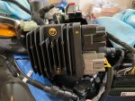
Follow by the battery regulator on the side of the battery cradle (the ProTi bolts is large on this unit, requiring 5Nm of torque), then I plug the 2 connectors:
IMG_3361.JPG

I finally ready to fix the rear bracket that hold the rear coils connector and what used to be the hoses for the secondary air injections solenoid, the ProTi on the top are 3Nm in torque while the 2 lower ProTi bolts were 4Nm in torque:
IMG_3362.JPGIMG_3363.JPG

Now, it is ready to accept the Rear Map Sensors and the Coil connector:
IMG_3364.JPGIMG_3365.JPG

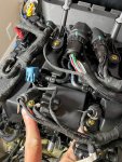
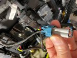
I then find one more blue connector to plug in, but I can't find anything to plug with it... then I realize, that is the connector for the secondary air injection solenoid and I need to plug it in with the jumper that came with the block off plate kit:
IMG_3366.JPG

Continue below...
 

BMW Alpina

FOUNDING Member & Administrator
Staff member
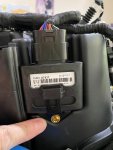
I review all around the airbox, to make sure I did not forget any bolts to torqued, and lucky I did that because turn out, I forgot to torque one more ProTi bolt for this control module:
IMG_3367.JPG

3Nm as usual for the M4 bolts...

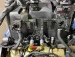
Took one picture to show the entire leftside of the airbox:
IMG_3368.JPG

Last, since it is getting closer to START the ENGINE again ... wow... I really forgot when I last heard the powerful noise of a V4 Ducati engine 😅 It's been more than a year since I last start the engine on my bike...
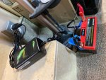
I need to make sure the battery is fully charged, so... I am charging it now 😎:
IMG_3369.JPG

There are still some more wires to secure on the rear subframe and also tie-locked... I think I will try to do it during the next few days 😃
 

BMW Alpina

FOUNDING Member & Administrator
Staff member
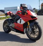
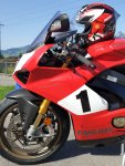
Hi Luz,
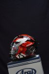
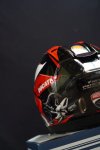
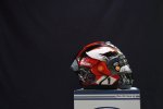
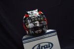
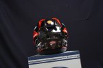
That is a very nice custom helmet :love:. May I know who made it for your?
Also, thank you for the pictures of your 916 anniversario, it had been a while since I saw my bike with all the fairings attached that I almost forget how my bike looks like 😅
Based on the number on your helmet, your bike is serial #169 (y)
 

Luz

New member
Hi, sure...the guy is called : Shin Abe and yes the serial is #169 (y)

He is from Indonesia here are his contacts:


Similar to my helmet always from him:


I had to wait 4 months for the work to be done...but it is incredible, 100% worth it to wait.


I cannot wait to finally see your bike fully dressed :)
 
Last edited:

BMW Alpina

FOUNDING Member & Administrator
Staff member
The Correct length Stahlbus quick bleeder for Brembo GP4-RR arrived, its M10x1.0-14 meaning M10 diameter, 1.0mm thread pitch and 14mm in length 🤓
IMG_3336.JPG

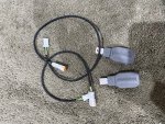
I also start installing the Bike Sport Development By Pass Module for the Ohlins Electronically Controlled Rear Shocks, notice it came with extensions cables:
IMG_3370.JPGIMG_3371.JPG

more significant updates soon 😎
 

BMW Alpina

FOUNDING Member & Administrator
Staff member
Today is another GREAT day since important parts arrived from Bike Sport Development in UK 😁
First, I must say that I am very satisfied with the Professional, Great Customer Service and Attention to Details from Mick Boasman, the owner of Bike Sport Development ! 👍🤝
And you guys will soon see why.

Here are the DHL box containing the SPECIAL CUSTOM Switches and more 😎:

IMG_3389.JPG

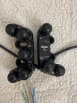
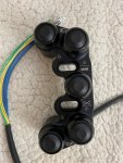
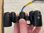
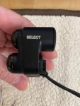
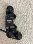
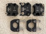
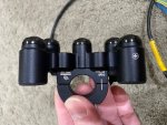
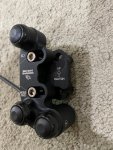
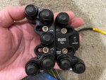
There are 2 custom switches to replace the entire left side switches:
IMG_3400.JPG

Let's pour into the details:
The 5 buttons switch were custom made according to my drawing and below is the picture of both the switches and the drawing that I made:

And you can see all the laser marking is exactly the way it is on the drawing that I made (again the right picture is the drawing that I personally made):
IMG_3394.JPG1633057915326.png

more details for the 5 buttons switch that show the laser marking on its side:
IMG_3395.JPGIMG_3396.JPG


Now lets review the 3 button switch shall we 🧐, the only changes that Mick recommended was to change the wording from Dual Function to "Mode CHG" due to space available and I agree,
If you notice, I also arrange the location of the switches that I need to access while riding on the 5 button switch since they will be located near my hand, while the 3 button switch is for function that not used often (at least not while riding).
The high light beam switch on the 3 button switch is for permanent high beam while the high light beam switch on the 5 button switch are for flashing high beam.
IMG_3398.JPG1633058075603.png

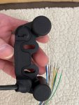
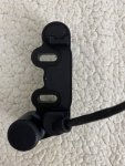
And this is the back side of both switches:
IMG_3397.JPGIMG_3399.JPG


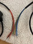
For ease of wiring, I also asked for specific color for the wires that correspond to specific button, and of course, the wire is the highest quality Raychem type 55 wire and DR25 sleeving:
IMG_3407.JPG

Then I order extra brackets so I have utmost flexibility when I mount it:
IMG_3401.JPG

Although for now it looks like my first choice of bracket (the Clutch CL-A and the universal BR-G) brackets will work fine:
IMG_3402.JPGIMG_3403.JPG

This is how they will be mounted side by side:
IMG_3404.JPG


Well to make it clearer, let me show you in front of the left handlebar, of course don't forget, they will be further modify with the addition of GOLD ProTi Titanium Bolts as usual 🤩🥳.
I am sooooo happy today because finally I will have "BALANCED" look on both handle bar, plus I will be the first in the world to have a custom left switches from Bike Sport Development 😉.
Now, I don't plan to wire them for now, I want to wait until after I take my bike to the dealership for uploading the Ducati Akrapovic Map, because I don't want the dealer to be too confused with the unfamiliar buttons locations since they might need to access some menu on the dashboard,
but take a look at those switches 🤓😄 Thanks Mick, I really appreciate your help in custom building this switches.
IMG_3405.JPGIMG_3406.JPG
 

BMW Alpina

FOUNDING Member & Administrator
Staff member
Weekend update 😁:

Today, I decided to work on the tie locking all the wiring and I start with the rear subframe wiring.

But first, I tie lock the wiring that goes to the rear subrame but start on the top of the airbox:
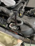
IMG_3424.JPGIMG_3425.JPG

IMG_3426.JPGIMG_3437.JPG

Oh, I also improvised a bit to secure the bypass plug for the secondary air injection connector:
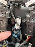
IMG_3427.JPG

Then secure the wiring loom to the subframe starting from the first securing point nearer to the engine and goes to the back:
IMG_3431.JPGIMG_3436.JPG
IMG_3438.JPGIMG_3440.JPG

Then I need to figure out where I am going to put the 2 Bike Sport Development rear Ohlins EC stock by pass module...
After looking at several alternative, I decided, first I need to run the wire to the back of the subframe, right under the main rear subframe wiring loom:
IMG_3449.JPG

Then I install the extension wire that came with the kit from Bike Sport Development all the way to the back, u-turn and goes to the right side of the subframe:
IMG_3450.JPGIMG_3442.JPG

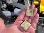
After that I am using the 3M Velcro to secure those modules to the right side of the Ilmberger carbon fiber rear subframe cover:
IMG_3444.JPG

IMG_3445.JPGIMG_3446.JPG
I choose this location for this module because it is quite protected from rain, and it still have plenty of airflow since this modules might get hot. I also don't want to put it right above the rear manifold (there is space there),
because that area might be too hot and not much air flow.

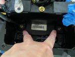
After that, I tightened the left rubber/plastic bracket for the CAN connector and also the rear tail light connector:
IMG_3441.JPG

Plus, I install the by-pass plug for the rear taillight, because the bike cannot have the taillight when the dealer installing the Akrapovic Up-map. Not due to technical issue, but due to the regulation that the up-map is only for track use bike.
IMG_3443.JPG

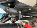
Oh, my heart skip a beat when I realize that I never test the rear subframe key... meaning I am not sure whether I can fit a key there with the Termignoni silencer bracket near it...
but to my relief, there is plenty of space to insert the key 😅:
IMG_3448.JPG

But then, my heart skip another beat because I realize the location of the O2 sensor on the SC-Project WSBK manifold is totally different than the location with the stock exhaust, and the length of the cable from the O2 sensor might not be enough to meet with the connector from the bike wiring loom side...
Furthermore, I am also not sure if the Ducati UP-MAP (Akrapovic) will require the removal of the O2 sensor...
So, I study the Installation Manual of the Ducati Akrapovic full system, and I found out the Akrapovic Full System still require the stock O2 sensor to be mounted and connected to the bike wiring loom.
The only strange (well maybe NOT IDEAL is the right word) for the Ducati Akrapovic Full System is, the O2 sensor only connect to 1 cylinder per bank.
For the rear cylinder bank, it connect to the RIGHT rear cylinder, and for the front cylinder bank, it connect to the RIGHT front cylinder.
Meaning the Left Cylinder of the front and rear bank does not have any O2 sensor monitoring.

The SC-Project WSBK exhaust on the other hand had 6 location, 4 per each bank and 2 more for either rear or front cylinder banks.
I decided to follow the stock exhaust configuration and install the 2 stock O2 sensors to measure both the rear and front cylinder banks on the SC-Project WSBK exhaust.
I think this is better than the way Ducati Akrapovic system O2 sensor location, according to Ducati Akrapovic install manual, although it might have holes for each cylinder banks, but I don't want to open the bubble wrap of the pipes to check since I already pack it well last time.

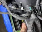
However, this means, I still need to REROUTE the wiring from the bike wiring loom for the rear cylinder bank O2 sensor from the original location near the rear exhaust manifold to the LEFT Side of the bike.
I found the best route is through the side of the front frame, but the space there is very tight and the connector size is quite big that it took me around 30 minutes to juggle and struggle and finally find a way to make it pass through.

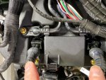
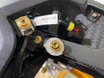
That include took of one of the airbox securing clamp, as you can see in the picture below, and that plastic connector is the big connector I am talking about:
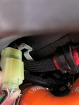
IMG_3432.JPG

after that, don't forget to push the airbox clamp back in secure position:
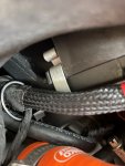
IMG_3433.JPG

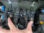
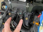
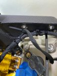
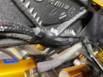
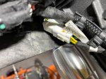
And here are the pictures that show where the connector from the wiring loom will meet it's counterpart from the O2 sensor. By the way at the bottom of this picture you also see the connector from the bike wiring loom for the front cylinder bank O2 sensor, which now has to go underneath the oil sump across the engine since the O2 sensor for the front cylinder bank is now located on the right side of the bike, right below the right rear set.
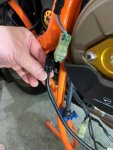
IMG_3434.JPG
 

Andy7

FOUNDING Member & Moderator
Staff member
The only strange (well maybe NOT IDEAL is the right word) for the Ducati Akrapovic Full System is, the O2 sensor only connect to 1 cylinder per bank.
For the rear cylinder bank, it connect to the RIGHT rear cylinder, and for the front cylinder bank, it connect to the RIGHT front cylinder.
Meaning the Left Cylinder of the front and rear bank does not have any O2 sensor monitoring.

The SC-Project WSBK exhaust on the other hand had 6 location, 4 per each bank and 2 more for either rear or front cylinder banks.
I’m surprised to hear that. Is that Ducati/Akrapovic being too lazy to develop a complete tune for the exhaust?
I mean, did they just kinda tweak what they already had from the previous generation maps to suit the v4 or immediately decide to 1/2 their development time by treating both banks as an average and say ‘that’ll be good enough for 95+%’ knowing most wouldn’t be too fussed having individual cylinder setups.
I hope my wording makes sense haha, been a big day riding and I’m nodding off while watching yesterdays wsbk carnage.
 
Top