DUCATI Panigale V4 25° Anniversario 916 BUILD Thread

BMW Alpina

FOUNDING Member & Administrator
Staff member
Hello everyone,

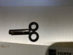
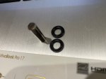
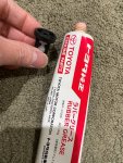
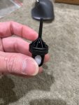
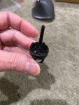
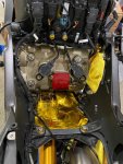
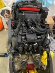
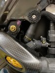
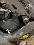
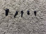
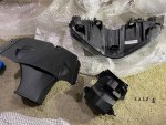
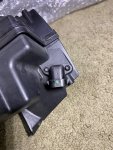
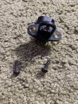
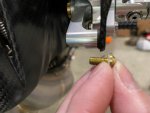
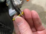
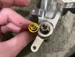
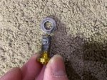
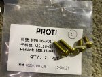
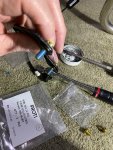
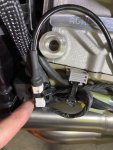
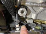
This is embarrassing, but somehow I totally FORGOT what the parts in the pictures below are for...
They are small stainless steel dowel with 2 rubber (almost like o-ring) but they are more like bushings.
If anyone remember what part these are for, please kindly help me 😅
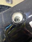
Oh, I found this together in the plastic bag where I stored the Ball and Cage for that drain/purge valve on the gas tank...
IMG_4381.JPG
IMG_4382.JPG
 

laid

New member
Hi Laid,
For the front Ohlins EC fork bypass module, I actually just installed it on show in on this same page of my build thread above, here is the link to this exact post: DUCATI Panigale V4 25° Anniversario 916 BUILD Thread

You can buy the module from Bike Sport Development in UK and please kindly mention to the owner Mick Boasman that you learn about the availability of this module in our forum 😃
Here is the link: KT142 - Ducati V4 DES Electronic suspension bypass kit - V4S Superbike, V4S Streetfighter
and in case you also want to replace the EC Ohlins steering damper, here is the module for it: KT148 - Ducati V4 Electronic steering damper bypass module

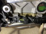
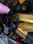
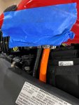
This is the picture of the module that I installed. It is literally just plug into the connector then you just have to find the right place to secure it somewhere near the battery.
thank you. Your work is very fast. It was very helpful.
It would be helpful if you could also tell me how to install the rear suspension.
I'm sorry to ask you many times.
 

BMW Alpina

FOUNDING Member & Administrator
Staff member
thank you. Your work is very fast. It was very helpful.
It would be helpful if you could also tell me how to install the rear suspension.
I'm sorry to ask you many times.
You mean the by pass module for the rear suspension?
It is exactly the same as the front, you just have to plug it in, and they use the same connector as the front.
Then you just have to find a place to hide it. I hide mine in the rear tail (right side) because they came with long wiring.
I posted the pictures in this build thread, many pages back.
I forget which pages though because as you know, this build thread is already 42 pages, so you just have to go back one page by one page until you find it ;)

Oh by the way Laid, please kindly post your build thread in our forum so we also can learn from your modification. Thanks
 

HKMP7

First 9 & Moderator
Staff member
Hello everyone,

This is embarrassing, but somehow I totally FORGOT what the parts in the pictures below are for...
They are small stainless steel dowel with 2 rubber (almost like o-ring) but they are more like bushings.
If anyone remember what part these are for, please kindly help me 😅
Oh, I found this together in the plastic bag where I stored the Ball and Cage for that drain/purge valve on the gas tank...
View attachment 6697
View attachment 6698
I have never seen that part so I'm not sure. I've had the bike pretty well apart and haven't seen that one. The only place I haven't really messed with is the airbox assembly.
 

BMW Alpina

FOUNDING Member & Administrator
Staff member
I have never seen that part so I'm not sure. I've had the bike pretty well apart and haven't seen that one. The only place I haven't really messed with is the airbox assembly.
Since now it is daylight, I see the part clearer. First I notice that one end is shaped different than the other end... then I realize, wait, I grinded one end of this, that is why...
Now, I am almost sure, this is one of the pin inside the link of the original chain (sprocket chain), and those 2 rubbers ring are the O-Ring for that link. It has grooves on it to store the chain lube...
I don't know why I stored this pin in the first place and not throw it away... maybe because I like the materials and want to keep it for reference...
Of course if someone else know what is this part for... (and if it is not the link for sprocket chain), then please let me know....

Hopefully @HKMP7 this is NOT part of the airbox / throttle body assy because... it is really a pain to disassemble everything to get there... 😅
I guess we will soon found out when I try to start the engine again hopefully tomorrow 🤩
 

BMW Alpina

FOUNDING Member & Administrator
Staff member
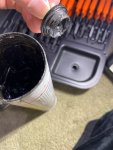
I am preparing the gas tank to install it on the bike again, so first replacing the drain plug with new parts.
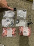
The parts in the plastic bags are all new parts, and the used parts are on the right side in this picture.
IMG_4369.JPG

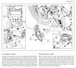
First install the ball inside the cage, just like in the PDF service manual on the background:
IMG_4370.JPG

Then seal it with the rubber spacer, and it was very tight so I improvise by adding rubber grease because I worry it might break the fragile thin looking plastic cage:
IMG_4371.JPG

Then cap it with the other plastic cage:
IMG_4372.JPGIMG_4373.JPG

Now, insert everything into the gas tank hole:
IMG_4374.JPG

Use Grease B liberally on both the plastic plug and on the O-Ring, (oh yes, you need to put the O-ring inside its groove first):
IMG_4375.JPG

Plug in the plastic plug, and you need to push and twist a bit hard to make it goes in completely. If it does not goes in completely, you can't lock it with the circlip.
IMG_4376.JPG

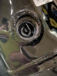
Lock using circlip:
IMG_4377.JPG

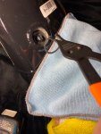
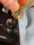
Then press again with flat screwdriver on the circlip to make sure it CLICK and SEAT inside the groove completely:
IMG_4378.JPG

Then CLEAN the airbox and the cylinder head cover one last time before you install the tank 🤩:
IMG_4379.JPG IMG_4380.JPG
 

BMW Alpina

FOUNDING Member & Administrator
Staff member
Next, I installed the gas tank on the frame, let me tell you, I missed that view :love:
It had been so long,... around 1.5 years without that gas tank on the bike 🥴
IMG_4383.JPG

and here are the details step:
Screw the right side mounting bracket of the gas tank with a ProTi bolts of course, then connect the fuel hose and clamp it:
IMG_4405.JPG

Then move to the left side and do the same thing with the mounting bracket, plus also install the ground cable:
IMG_4410.JPG

Then goes to the back and install the 2 other ProTi bolts with washer to secure the gas tank to the frame:
IMG_4406.JPG

Then install the breather hose to the canister and clamp it:
IMG_4408.JPG

I still need to install the fuel overflow hose (will be using Samco, and I will do it tomorrow)...

Next, I am working on the FRONT intake that attached to the headlight. First I disassemble them and turn out, you will need a long head torx screwdriver otherwise, it won't fit:
IMG_4387.JPGIMG_4386.JPG

You need to take out all 6 screws otherwise, it won't disassemble:
IMG_4388.JPG

Everything separated:
IMG_4389.JPG

Then took out the Air Temperature Sensor from the older part# resonator:
IMG_4390.JPGIMG_4391.JPG

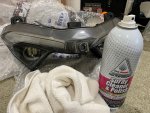
Next, clean the dusty headlight with Honda Cleaner:
IMG_4392.JPG

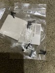
Prepare all brand newer self taping screws, just because I prefer to use newer screws
IMG_4393.JPG

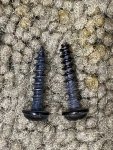
Only to find out that the screws originally came with the bike have better design (the end is dull not sharp so it should have a bit more grip), so I decided to reuse the old screws:
IMG_4394.jpg

Then when I try to fit the NEWER Part# resonator to the Superleggera V4 Carbon Fiber Air Intake, it just won't fit because the carbon fiber have some corner too thick.
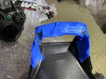
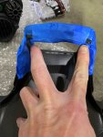
So I masked the area with blue painters tape to protect against accidentally dremel those area, and let the area where I want to grind open:
IMG_4395.JPGIMG_4396.JPG

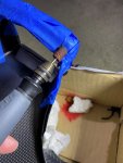
Start grinding with Dremel:
IMG_4397.JPG

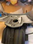
and Voila, now the resonator FIT well:
IMG_4398.JPG

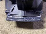
But, then I need to recoat the grinded area of the Carbon Fiber surface with a Resin/Polymer:
IMG_4399.JPG

I made a bit to much so I also coat the rough surface on the resonator to make it smoother:
IMG_4400.JPG

Then I put both under light to speed up it's drying process so hopefully I can joined them together by tomorrow:
IMG_4401.JPG

continue below...
 

BMW Alpina

FOUNDING Member & Administrator
Staff member
IMG_4402.JPG

I also take picture of the left and right side of the old resonator because the tie-lock clamp position is different between left and right side just for my reference:
IMG_4403.JPGIMG_4404.JPG


More updates tomorrow, time to go to sleep now 😴
 

BMW Alpina

FOUNDING Member & Administrator
Staff member
Oh by the way, this past few weeks, we have many new members joining our forum.
On behalf of all the moderators and founders of this forum, we would like to say welcome again and thank you for choosing to join DUCATImodified.com forum.
Please don't forget to start your build thread, so we all can learn from each other.
 

ggok

Active member
Next, I installed the gas tank on the frame, let me tell you, I missed that view :love:
It had been so long,... around 1.5 years without that gas tank on the bike 🥴
View attachment 6713

and here are the details step:
Screw the right side mounting bracket of the gas tank with a ProTi bolts of course, then connect the fuel hose and clamp it:
View attachment 6714

Then move to the left side and do the same thing with the mounting bracket, plus also install the ground cable:
View attachment 6715

Then goes to the back and install the 2 other ProTi bolts with washer to secure the gas tank to the frame:
View attachment 6716

Then install the breather hose to the canister and clamp it:
View attachment 6717

I still need to install the fuel overflow hose (will be using Samco, and I will do it tomorrow)...

Next, I am working on the FRONT intake that attached to the headlight. First I disassemble them and turn out, you will need a long head torx screwdriver otherwise, it won't fit:
View attachment 6718View attachment 6719

You need to take out all 6 screws otherwise, it won't disassemble:
View attachment 6720

Everything separated:
View attachment 6721

Then took out the Air Temperature Sensor from the older part# resonator:
View attachment 6722View attachment 6723

Next, clean the dusty headlight with Honda Cleaner:
View attachment 6724

Prepare all brand newer self taping screws, just because I prefer to use newer screws
View attachment 6725

Only to find out that the screws originally came with the bike have better design (the end is dull not sharp so it should have a bit more grip), so I decided to reuse the old screws:
View attachment 6726

Then when I try to fit the NEWER Part# resonator to the Superleggera V4 Carbon Fiber Air Intake, it just won't fit because the carbon fiber have some corner too thick.
So I masked the area with blue painters tape to protect against accidentally dremel those area, and let the area where I want to grind open:
View attachment 6727View attachment 6728

Start grinding with Dremel:
View attachment 6729

and Voila, now the resonator FIT well:
View attachment 6730

But, then I need to recoat the grinded area of the Carbon Fiber surface with a Resin/Polymer:
View attachment 6731

I made a bit to much so I also coat the rough surface on the resonator to make it smoother:
View attachment 6732

Then I put both under light to speed up it's drying process so hopefully I can joined them together by tomorrow:
View attachment 6733

continue below...
According to the instruction manual, remove the Canister from the car body when the akrapovic exhaust is installed.

Even if it is a standard ECU mapping and standard exhaust, it is less likely to cause problems if it is removed.
It is illegal depending on the country or region😜
スクリーンショット 2021-12-04 224207.jpg
スクリーンショット 2021-12-04 224027.jpg
 

BMW Alpina

FOUNDING Member & Administrator
Staff member
Thanks ggok, but since my bike is permanently on duty as living room display, I prefer to keep the fuel tank canister because I don't want my living room to smell like gas station 😅
 

BMW Alpina

FOUNDING Member & Administrator
Staff member
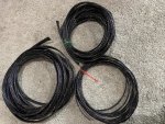
Bunch of TechFlex Flexo PET cable sleeving in UpTown Gold colors arrived for my supply and also for cable sleeving all the wiring from the Bike Sport Development UK switches 🤩:
IMG_4433.JPG
more updates coming soon today ;)
 

BMW Alpina

FOUNDING Member & Administrator
Staff member
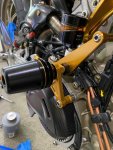
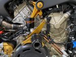
Ok, the AELLA frame slider was one of the very first item that I ordered for my bike almost 2 years ago.
In fact, I wasn't planning to modify my bike too much initially... just some AELLA frame slider to protect it... but I guess I got carried away (in a good way) ;)

Now, due to all the steps, and all the mistakes in ordering the correct length of ProTi bolts... well it is not really a mistake, but I want to have the maximum length available for each bolts,...
the Right Side AELLA frame slider was never completely installed until today... yap... it had been test fit many times but only today, I finally finished it's installation PERFECTLY 🥳

Why... well here is why...

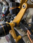
First, I need to replace the center bolt that hold the Rizoma mirror bracket that hold the Ducati by Rizoma rear brake reservoir with a ProTi bolts that have the correct maximum length for maximum thread engagement and the right head shape and as you can see below, I am replacing the ProTi bolts that I am holding in my finger with the ProTi bolt with larger diameter head and 5mm longer (total of 45mm length) that is already installed on the Rizoma mirror bracket:
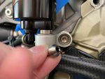
IMG_4441.JPG
So why this caused delay to installing the RIGHT side AELLA frame slider? well because the AELLA frame slider location BLOCK access to this Rizoma mirror bracket so I need to finish with this mirror bracket bolt first before I can install the RIGHT side AELLA frame slider permanently.

And after this, there are another 3 bolts that hold the full six/shiftech carbon fiber brake hose bracket, which also partly blocked by the AELLA Right Frame Slider, meaning I better replace these 3 bolts first.
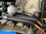
IMG_4437.JPG

These 3 Silver ProTi bolts were part of the kit from ProTi and they are TOO SHORT. So I replace them with a Gold ProTi with 2mm more length to 14mm:
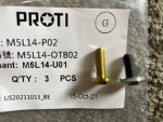
IMG_4438.JPG

And the result 🤩:
IMG_4439.JPG

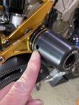
Then finally, I can install the AELLA Right Frame Slider permanently. Now, due to the protrusion of the Rizoma Mirror Bracket that hold the Ducati by Rizoma brake reservoir,
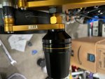
I need to add SPACERS to the AELLA frame sliders to clear it, and here is the clearance after the spacers (pointed by my fingers)... I guess, I measured right down to the mm for the just the right clearance 🧐:
IMG_4445.JPG

And here are the spacers (note they are all STAINLESS Steel spacer because I like the finish better than an aluminum spacers):
Top right side spacer with ProTi M6L70-OTB01 in Titanium Silver:
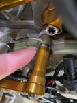
IMG_4446.JPG

Top left side spacer with ProTi M6L75-OT01 in Titanium Silver:
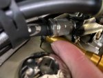
IMG_4447.JPG

Lower Left Side spacer with ProTi M6L45-OT02 in Titanium Silver:
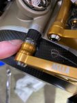
IMG_4448.JPG

Lower right side spacer M6L45-OT02 in Titanium Silver:
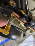
IMG_4449.JPG

Here are the AELLA instruction manual, all the M6 bolts need to be torqued to 10Nm and the main center M8 bolts to 18Nm:
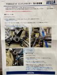
IMG_4462.JPG

For the right side spacer, you will need to install the 2 top bolts first and tightened them to 10Nm.

Then, you need to position the center cylinder (of the slider) and tightened it to 18Nm.
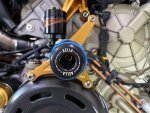
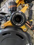
Since the face of the slider cylinder have a very nice "AELLA" white color laser marking, I want to make it perfectly align horizontally when the bike both tires are on the ground.
So I asked my oldest son to hold the bike (without any stand) with both wheel on the ground, then I use rubber band so my left hand can have enough grip to hold the main slider cylinder while align the "AELLA" laser marking, with my right hand using a torque wrench to tightened it to 18Nm.

Here is the picture of the blue rubber band to help with grip:
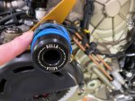
IMG_4442.JPG

and here is after centered:
IMG_4443.JPG

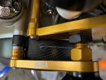
by screwing this center bolt as much in as possible, it also self aligned the two lower bracket, and now you can tightened the two lower M6 bolts to 10Nm.

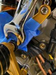
Next, you need to LOCK the center bolt with a lock nut and make sure you add a lot of Painter's tape to protect the surface in case your open ended wrench slipped (knock on carbon fiber errr wood) 😅:
IMG_4444.JPG

Finally everything is finished and after a few dash of Honda Cleaner:
First notice how nice the AELLA "carve the dream" white laser marking at the end of the cylinder slider... that is why I want them to be align perfectly with both wheel on the ground 😎
IMG_4454.JPG

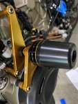
Then, how about that Gold Trim RING surrounding the main slider cylinder... it add a classy touch combined with the another AELLA laser marking and that "Ducati Performance" logo on the background 🤩:
IMG_4455.JPG

another angle:
IMG_4456.JPGIMG_4459.JPG

From the front:
IMG_4457.JPGIMG_4461.JPG
IMG_4458.JPG

Yap, I think it is PERFECT, ... until I realize.. that there is one hole on the side of the slider cylinder, maybe for a screw driver to plug into to help align instead of my method of using rubber band...
and this hole on the right side is facing the front... which means if I ride the motorcycle, all the wind will bring dust into the center of the cylinder...
yap... after all the effort aligning above, I realize, I made a mistake,... so I corrected it my rotating the slider cylinder 180 degrees and make the hole facing backward of the bike like on the picture below,... and now I finally can say, IT's PERFECT 😉:
IMG_4463.JPG

Pheew... so these are all the things that I am willing to do just for a PERFECT Right Front Slider Install...😌

Days are still young everyone so more updates later today....
 

BMW Alpina

FOUNDING Member & Administrator
Staff member
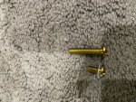
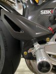
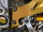
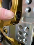
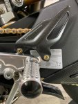
Then I replace the ProTi bolts that came with ProTi kit for heel guard to a proper length.
First the right side, below is the picture of the original M5 x 10mm bolt that came from ProTi as their kit for heel guard,
IMG_4464.JPG

Next is the longer ProTi bolt M5L25-OTB05 (yes 25mm long) but it will engage the entire available thread on the right Ducati by Rizoma rear sets, so this is PERFECT:
IMG_4466.JPG

Just to put the length differences into perspective:
IMG_4465.JPG

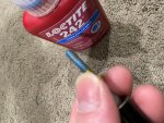
Use Loctite of course, and tightened to 5Nm. Now the original install manual of Ducati Performance Carbon Fiber Heel Guard said 8Nm, but that can't be right.
Because, first of all, for every other M5 bolts that came with other Ducati Performance carbon fiber kit, they all specified up to only 5Nm. While if the bolt is M6, then it will be 8Nm.
so somehow the person who wrote this Ducati Performance Carbon Fiber Heel Guard install manual must mistakenly put 8Nm.
Another red sign is on ProTi website, you can see that the safe torque for their M5 bolt is only 7Nm, so of course 8Nm might snap the M5 Titanium Bolt.
IMG_4467.JPG

Installed on the right side:
IMG_4468.JPG

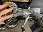
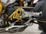
Then its time to move to the LEFT side rear set:
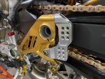
First, I replace the M8 bolts (20mm) that hold the foot peg with the version with larger head for more even load distribution, you can see the differences, the Gold bolt is the new larger diameter head version:
IMG_4469.JPG

I use antiseize and also TITANIUM washer, (yes that washer is Titanium) because 20mm is a bit too long for the thread but with the addition of the washer, the bolt is the right length now:
IMG_4470.JPG

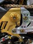
Now, I install the multi position adjustable plate of the Ducati by Rizoma left rear set to the Motocorse Side Plate using ProTi with Grease B and 25 Nm of torque.
IMG_4471.JPG

Oh, I forgot, before I did the above, I actually already tightened the 2 bolts that hold the Motocorse side plate to the frame at 25Nm (with Grease B):
IMG_4472.JPG

And I also tightened the single bolt that clamp the Motocorse side plate to the rear swing arm axle, but this one only at 21Nm with Grease B.
Make sure you do not exceed 21Nm because unlike the other bolt, this one is for clamping:
IMG_4473.JPG

Next the 2 bolts holding the final part of the left rear set, of course Grease B and 25Nm:
IMG_4474.JPG

For the left side rear set, the bolt that hold the Ducati Performance Carbon Fiber heel guard is shorter at just 16mm, still much longer than the stock 10mm in comparison picture below:
IMG_4475.JPG

Don't forget Loctite and 5Nm again, and voila:
IMG_4476.JPGIMG_4477.JPG

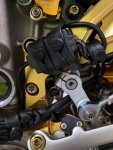
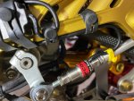
Now, time to attached the bolt that hold the Cordona Quick Shifter to the shift shaft lever. Use Loctite, don't forget the Nylon Washer, and tightened to 10Nm:
IMG_4478.JPG

I test fit and tightened the locking nut to 5Nm:
IMG_4479.JPG

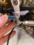
Now, the fun stuff, routing the wire of the Cordona Quickshifter and find the best place that will prevent the Cordona module from getting damage by the exhaust heat.
So first, I connect the socket from Cordona Quickshifter to the bike wiring and tigthened it at the PROPER spot with a tie lock:
IMG_4480.JPG

Routed as a U-Shape:
IMG_4481.JPG

Apply all the tie-lock and rubber band to make sure all the wiring are SECURED:
IMG_4483.JPG

After many test fits, I finally decided I am going to place the Module on the Motocorse side plate. The Cordona quickshifter kit came with a 3M Velcro. I attached the adhesive to the Cordona module,
but the other side, I did not release the tape that cover the adhesive because I don't want the adhesive to smear the Motocorse side plate, plus I might need to remove the Cordona module again.
I firmly hold it using the 2 rubber band. So you ask, why the need to attached the 3M Velcro to the back of the Cordona module in the first place?
Well it support many functions, as vibration dampener and to prevent head from the Motocorse side plate to transfer to the Cordona module:
IMG_4490.JPG

More pictures that show how I route the wiring:
IMG_4489.JPG

more pictures below:
 

BMW Alpina

FOUNDING Member & Administrator
Staff member
IMG_4492.JPG

This is how it looks:
IMG_4493.JPG

But wait, that center hole of the rear swing arm axle is not a good sight... but wait.. I have the Motocorse rear swing arm axle plug cover... I just need to find it somewhere...
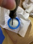
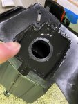
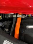
and a few minutes of searching... I manage to find it and install it and now this is how it looks:
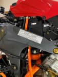
IMG_4494.JPG

IMG_4496.JPG

IMG_4495.JPG

Now, Motocorse supposed to release a BILLET side stand soon, and if I like the style, then I will replace this stock silver Panigale V4 side stand with Motocorse version in gold color... but if I don't like the style, then I will keep this side stand since it already looks good.
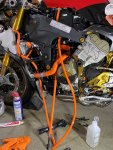
Ok, another task for this weekend done... now time to work on the drain hose for fuel over flow from the gas tank... more updates coming 😃
 

BMW Alpina

FOUNDING Member & Administrator
Staff member
amazing how quickly its all coming back together again. I can't wait to see you fire it up
Me too Andy, hopefully tomorrow (if I did not made any mistake with the throttle body or any of the wiring 😅 )

On that note, I just install the Samco hose for the fuel tank overfill drain. Since this hose will be exposed to gasoline, I can't just use Samco regular silicone hose.
There are 2 choices:
a. SamcoSport Fluorolined Silicone Hose Lengths specially designed for applications where traces of oil and diesel will be in contact with the hose
b. SamcoSport ProFuel™ Silicone Hose Lengths specially designed for petrol applications

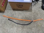
Initially, I did not know about SamcoSport ProFuel™, so I purchased the SamcoSport Fluorolined Silicone Hose.
In fact I already made the line combined with original stock rubber line for coolant overflow in picture below:
IMG_4498.JPG

But then I found out and decided to purchase the SamcoSport ProFuel™ since that is the one with the best compatibility with gasoline/fuel.
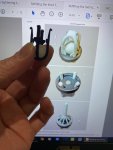
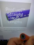
If you notice the SamcoSport ProFuel™ had inner lining in GREEN color. I took picture of the hose I have with the background picture from the screen of my laptop,
but in this picture below is really me holding my SamcoSport ProFuel™ hose:
IMG_4497.JPG

I use several layer of blue painters tape on the tank, just to protect it in case somehow my hand/tool missed and hit the tank.
Also the best way to route this thick silicone hoses is to push it from top of frame going down. Also apply a bit of WD40 to help with a bit more slippery when you route the hose.
If you notice, I did not replace the hose that is going to the EVAP canister. The reason is because I worry the plastic nipple of the EVAP canister to be easily broke when / if I tried to pull the original hose from it.
The routing of the original rubber hose of the EVAP canister is also a bit more complicated, so after carefully thinking about it, I decided, to let this one go. Better to have a working EVAP canister then risk of breaking it and have to take out the whole tank/airbox/throttle body again just to fix it.
IMG_4499.JPG

Once I am done with tightening the clamp for the overfill fuel drain hose, I took out the blue painters tape and the result is great.
Also if you notice, I don't think there is enough space to place another thick silicone hose since the spacing of the nipple for the EVAP and overflow drain nipple is too close apart:
IMG_4500.JPG

More pictures:
IMG_4501.JPGIMG_4502.JPG

Tomorrow, I am going to measure and cut the hoses for this fuel overfill drain hose and the coolant overflow hose with a Y stainless steel connector tomorrow, so it's setup exactly like the factory setup.
After that, I just need to install the front intake/resonator assembly with the headlights, connect the Air temperature sensor, fill the gasoline, and CLEAN the SC-Project exhaust Titanium Piping with Alcohol to make sure they are clean before they got heated when I start the engine.
Time to go to sleep now 😴
 
Top