Grab yourself some popcorn this might take a while!
- Thread starter topolino
- Start date
topolino
Well-known member
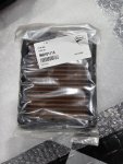
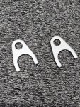
Oil cooler pipe retention plates. Cerakoted in "Glacier Silver"
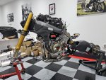
Here's the bike as it currently stands. Note the MotoCorse rear frame plugs. The front frame bolts are only temporary until the MotoCorse frame plugs arrive to replace them.
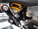
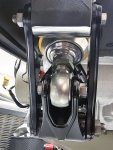
And here is a gratuitous shot of the rear linkage again. It's a thing of beauty.

Here's the bike as it currently stands. Note the MotoCorse rear frame plugs. The front frame bolts are only temporary until the MotoCorse frame plugs arrive to replace them.

And here is a gratuitous shot of the rear linkage again. It's a thing of beauty.

topolino
Well-known member
Time to crack on by turning my attention to the cooling system and assemble the new Evotech Performance "EP" edition guards. Essentially the same as standard but with a large logo on the radiator guard and a revised logo and spacer fittings on the oil cooler guard.
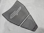
With the spacer rubbers fitted. Two additional (hidden) spacers clip into the back of the logo plate on the oil cooler
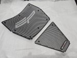
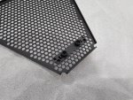
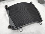
Here is the radiator and oil cooler after Cerakotiing (Glacier Satin Black).
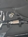
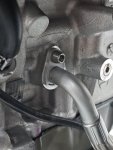
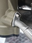
Silicon bungs, prevent any residual oil from leaking out until I am ready to connect the lines.
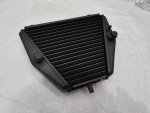
The radiator guard contrasts well against the black Cerakote finish
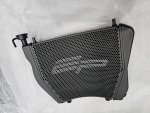
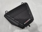
Rubber dampers and steel bushings need to be refitted, then I can assemble both the radiator and the cooler back onto the shroud, as well as the cooling fan assembly.
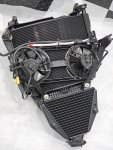
Here's the net result. Still a few mods to make to some of the coolant lines (remaining part of the Samco kit) but it is largely ready to go back on the bike.
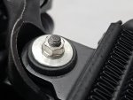
M5 stainless steel flanged nuts (Stig Fasteners) torqued to 5Nm
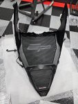
This tie wrap holds the clutch line to the top of the radiator bracket and is a complete PIA to secure if you don't pre-feed the tie wrap in first.
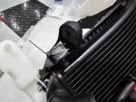

With the spacer rubbers fitted. Two additional (hidden) spacers clip into the back of the logo plate on the oil cooler


Here is the radiator and oil cooler after Cerakotiing (Glacier Satin Black).

Silicon bungs, prevent any residual oil from leaking out until I am ready to connect the lines.

The radiator guard contrasts well against the black Cerakote finish


Rubber dampers and steel bushings need to be refitted, then I can assemble both the radiator and the cooler back onto the shroud, as well as the cooling fan assembly.
Here's the net result. Still a few mods to make to some of the coolant lines (remaining part of the Samco kit) but it is largely ready to go back on the bike.

M5 stainless steel flanged nuts (Stig Fasteners) torqued to 5Nm


This tie wrap holds the clutch line to the top of the radiator bracket and is a complete PIA to secure if you don't pre-feed the tie wrap in first.

topolino
Well-known member
topolino
Well-known member
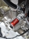
Clutch line fitted and Stahlbus bleeder/banjo bolt.
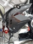
Front sprocket torqued to 55Nm, then fitted the Ilmberger carbon sprocket cover, remaining two Pro Bolts torqued to 10Nm.
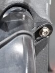
P08 Sprint filter fitted and front air duct secured using RaceTi M5 x 15mm flanged torx bolts, torqued to 6Nm.
One of the advantages of using the Akrapovic exhaust system is that all the additional hardware that takes account of the exhaust valve removal and EVAP canister are included in the kit. At least with the full system. However having decided to go down the Termignoni route, I have had to source all these parts myself, so if you are planning on doing something similar, you will typically need some or most of these parts. I've already touched on the new ABS bracket, but I will highlight other components that you may need and their part numbers.
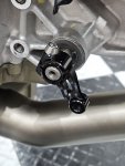
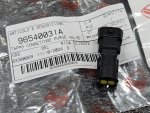
Here is one such example. This plug is for the now defunct purge circuit return line.
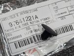
Purge valve delete connector

Front sprocket torqued to 55Nm, then fitted the Ilmberger carbon sprocket cover, remaining two Pro Bolts torqued to 10Nm.

P08 Sprint filter fitted and front air duct secured using RaceTi M5 x 15mm flanged torx bolts, torqued to 6Nm.

One of the advantages of using the Akrapovic exhaust system is that all the additional hardware that takes account of the exhaust valve removal and EVAP canister are included in the kit. At least with the full system. However having decided to go down the Termignoni route, I have had to source all these parts myself, so if you are planning on doing something similar, you will typically need some or most of these parts. I've already touched on the new ABS bracket, but I will highlight other components that you may need and their part numbers.
Here is one such example. This plug is for the now defunct purge circuit return line.


Purge valve delete connector


topolino
Well-known member
Here is the splitter and shorter drain tubes, that convert the dual line setup from the fuel tank into a single line, where previously there were two separate lines. One for the EVAP canister and one for the fuel drain.
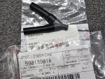
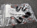
These Pclips are used to secure the LHS lower wiring to the engine. More importantly to keep it clear of the exhaust front headers.
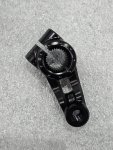
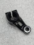
Next from MotoCorse, this new billet alloy gear change arm.

These Pclips are used to secure the LHS lower wiring to the engine. More importantly to keep it clear of the exhaust front headers.

Next from MotoCorse, this new billet alloy gear change arm.


topolino
Well-known member
More MotoCorse parts. This time it's the LHS support plate. This comes in two pieces as it features an optional side stand delete section for track days (if that's what you need).
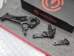
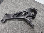
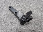
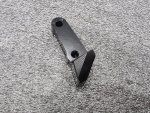
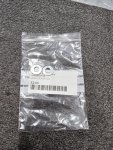
Since the stock exhaust is history, you have to fit two washers behind the front two mounting bolts of the plate, to space it out correctly. These are normally supplied in the Akrapovic kit. They replace the stock OEM exhaust hangar plate of the same thickness.
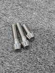
Three mounting bolts. Pro Bolt 2 x M8 x 35mm and 1 x M8 x 20mm. Torqued to 25Nm and 20Nm respectively.
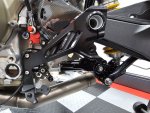
Here's the plate fitted to the bike.
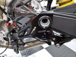
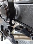
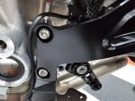


Since the stock exhaust is history, you have to fit two washers behind the front two mounting bolts of the plate, to space it out correctly. These are normally supplied in the Akrapovic kit. They replace the stock OEM exhaust hangar plate of the same thickness.

Three mounting bolts. Pro Bolt 2 x M8 x 35mm and 1 x M8 x 20mm. Torqued to 25Nm and 20Nm respectively.

Here's the plate fitted to the bike.


Could you lobby
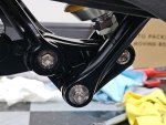
Would you mind popping the link to the M8 x 25 bolts please? They look more like the x 30?Decided rather than Cerakote the OEM parts as on my previous build, which looked "OK", I've replaced them entirely with these billet aluminium parts from MotoCorse, which are in a different league altogether.
Lower rear suspension support bracket
View attachment 14453
View attachment 14454
Upper rear suspension support bracket
View attachment 14455
View attachment 14456
Upper bracket fitted to the bike. Top two bolts (Pro Bolt M8 x 25mm) torqued to 30Nm. Lower bolt to 35Nm.
View attachment 14457
Lower bracket fitted to the bike. All three bolts torqued to 35Nm. (Pro Bolt M8 x 25mm). The eagle-eyed amongst you may notice the two pin studs on the gear position sensor. These are to mount the cooling duct that was introduced on later Panigales, to offset overheating problems, that in the past resulted in failures of the unit.
View attachment 14458
These brackets have to be fitted before the swingarm can go back on, else it is impossible to access the central two bolts where the two parts meet.
View attachment 14459
Next up will be the rocker arm and link rods then the swing arm can go back on, followed by the rear shock absorber. Because the torque values for the 3 x M12 bolts that hold the rear suspension linkages together are so high, these will be tightened once the assembly is complete, with suspension unloaded/supported. Since I am waiting on more parts, I will turn my attention to some other sub-assemblies, that I can work on in the meantime.
topolino
Well-known member
With the plate fitted I could turn my attention to the LHS lower wiring loom, which includes the sidestand switch, gear position sensor, quickshifter and cylinder 1 lambda sensor. The first two need to be wrapped in a heat reflective blanket before the rest can be tidied up, as per the factory specs. The main aim is to minimize direct exposure to heat by standing them off from the engine, as best as is possible. First job was to fit the sidesstand switch, using Pro Bolt M4 x 10mm titanium screws, torqued to 2Nm and a dab of Loctite 243.
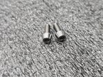
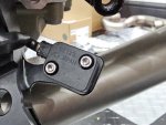
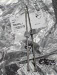
Purchased a new set of Hellerman ties to secure the wiring in place as per the workshop manual.
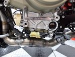
Wiring all buttoned up.
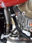
P-clip held in place with Pro Bolt M6 x 15mm bolt torqued to 10Nm. This ensures the wiring is kept well away from the front headers.
Next job was to fit the new single fuel tank drain line and connect it, as well as the airbox drain line and water pump drain line to the outlet which is located at the bottom of the oil cooler. This much improved design was introduced on the 2022 models. Earlier versions had the drain lines attach to the fairing lowers.
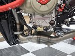
Next job was to fit the support plate plugs from Moto Corse.
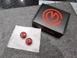
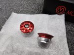
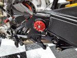
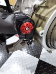
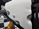
Finally I replaced the expansion tank bolts on both sides, with ones from Pro Bolt. M5 x 20mm, torqued to 2.5Nm.
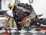
So here is where I am at so far. Only the quick shifter load cell to attach and the QS, plus the LHS rearset and the gear position sensor cooling duct, then this side is almost complete. You'll obviously notice that the cooling system is also now installed as well as 99% of the SAMCO pipework.
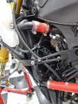
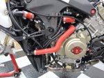
Clutch line fastened to engine casing. Much better design than on older models.
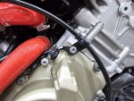
The next stage is over on the RHS of the bike, where I need to install the ABS unit, hydraulic lines and connect up the three remaining Lambda sensors, front and rear wheel speed sensors, brake light switch. RPM pick up sensor and oil pressure sensor, as well as blank off the exhaust valve motor connection.


Purchased a new set of Hellerman ties to secure the wiring in place as per the workshop manual.

Wiring all buttoned up.

P-clip held in place with Pro Bolt M6 x 15mm bolt torqued to 10Nm. This ensures the wiring is kept well away from the front headers.

Next job was to fit the new single fuel tank drain line and connect it, as well as the airbox drain line and water pump drain line to the outlet which is located at the bottom of the oil cooler. This much improved design was introduced on the 2022 models. Earlier versions had the drain lines attach to the fairing lowers.

Next job was to fit the support plate plugs from Moto Corse.


Finally I replaced the expansion tank bolts on both sides, with ones from Pro Bolt. M5 x 20mm, torqued to 2.5Nm.

So here is where I am at so far. Only the quick shifter load cell to attach and the QS, plus the LHS rearset and the gear position sensor cooling duct, then this side is almost complete. You'll obviously notice that the cooling system is also now installed as well as 99% of the SAMCO pipework.


Clutch line fastened to engine casing. Much better design than on older models.

The next stage is over on the RHS of the bike, where I need to install the ABS unit, hydraulic lines and connect up the three remaining Lambda sensors, front and rear wheel speed sensors, brake light switch. RPM pick up sensor and oil pressure sensor, as well as blank off the exhaust valve motor connection.
topolino
Well-known member
So started to make s some real strides today. First off was sorting out the RHS lower wiring branch and connectors. This is a bit of a viper's nest of wiring so I took my time to make sure everything was routed as it should be allowing for correct positioning of each connector/sensor and cable management to make the end result as neat as possible.
First things first was to route the no.2 Lambda sensor wiring as this sits behind the ABS support bracket and the front wheel sensor which has to be fed in behind the front frame.
ABS support bracket is held in place with two bolts. I replaced the gash OEM ones with these RaceTi torx flanged titanium bolts, torqued to Nm and a dab of Loctite 243.
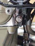
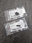
Here are another two parts, normally found in the full Akrapovic kit, which I had to source. These being the exhaust valve servo blanking plug and the rubber strip that prevents the lower fairing rubbing on the ABS support bracket (this has to be bonded onto the bracket, which I will do tomorrow).
Some TESLA fabric tape on the exhaust servo valve blanking plug/connector, to neaten things up.
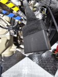
Here's the finished result. I amongst this cluster are the RPM pick up sensor, oil pressure switch, front and rear wheel speed sensors, fan power supply connector, no.2 cylinder Lambda sensor, ABS unit main connector and servo valve blank. I also fitted colour coded spiral binding to each hydraulic line instead, as I am not a fan of the sticky tape Ducati method Ducati uses.
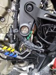
Next job was to sort out the wiring to the swingarm, namely the rear wheel speed sensor and the rear caliper hydraulic line.
This cover has been redesigned on later models and now features an extra heat reflective sheath over the speed sensor cable and hydraulic line, which the workshop manual goes into very specific detail about, showing where and how to fit it with precise positioning on the speed sensor cable, that must align with existing marks. OEM bolts torqued to 5Nm and a dab of Loctite 243.
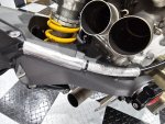
The speed sensor cable/rear hydraulic line, MUST be routed under the chain slider lip before finally torqueing down the remaining rear most upper dome head bolt (5Nm and Loctite 243).
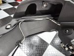
First things first was to route the no.2 Lambda sensor wiring as this sits behind the ABS support bracket and the front wheel sensor which has to be fed in behind the front frame.
ABS support bracket is held in place with two bolts. I replaced the gash OEM ones with these RaceTi torx flanged titanium bolts, torqued to Nm and a dab of Loctite 243.

Here are another two parts, normally found in the full Akrapovic kit, which I had to source. These being the exhaust valve servo blanking plug and the rubber strip that prevents the lower fairing rubbing on the ABS support bracket (this has to be bonded onto the bracket, which I will do tomorrow).

Some TESLA fabric tape on the exhaust servo valve blanking plug/connector, to neaten things up.

Here's the finished result. I amongst this cluster are the RPM pick up sensor, oil pressure switch, front and rear wheel speed sensors, fan power supply connector, no.2 cylinder Lambda sensor, ABS unit main connector and servo valve blank. I also fitted colour coded spiral binding to each hydraulic line instead, as I am not a fan of the sticky tape Ducati method Ducati uses.

Next job was to sort out the wiring to the swingarm, namely the rear wheel speed sensor and the rear caliper hydraulic line.
This cover has been redesigned on later models and now features an extra heat reflective sheath over the speed sensor cable and hydraulic line, which the workshop manual goes into very specific detail about, showing where and how to fit it with precise positioning on the speed sensor cable, that must align with existing marks. OEM bolts torqued to 5Nm and a dab of Loctite 243.

The speed sensor cable/rear hydraulic line, MUST be routed under the chain slider lip before finally torqueing down the remaining rear most upper dome head bolt (5Nm and Loctite 243).

topolino
Well-known member
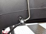
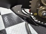
With that job done I had to fit the rear carbon shark fin chain guard. This is held in place by the hydraulic line p-clip on the swing arm and on the underside by the rear most chain slider bolt and an additional bolt. All three torqued to 5Nm and Loctite 243. The guard was transferred across from the previous bike but I had it clear coated again as the lacquer had been chipped at some point.
Underside fixing
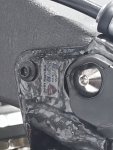
Additionally secured by the P-clip on the swing arm.
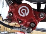
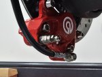
With this out the way it was time to plumb the rear caliper in. This time using a Racebolt stainless steel banjo bolt (torqued to 24.5Nm, was 23Nm on older variants) and fitted the Stahlbus speed bleeder valve and cap (not shown in this pic).
Rear wheel speed sensor fitted (including shims) using Pro Bolt M6 x 15mm flanged hex bolt, torqued to 8Nm.
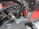
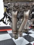
With the wiring/lines to the swingarm fitted, I could then continue assembly of the exhaust, as fitting it would have made the previous work very awkward.
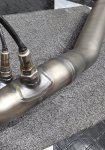
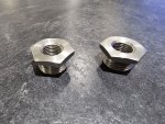
Cylinders 3 & 4 Lambda probes fitted, using bung adaptors previously mentioned.
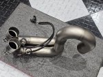
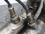
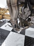
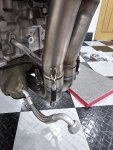
I then spent the next hour or so trying to get this section to fit to the rear headers before discovering that this system requires some degreee of "persuasion" and is by no means easy to install, due in part to it's somewhat liberal tolerances but it all went on as intended eventually. I will upload some more images shortly.
As for the RHS lower wiring all that is left to do now, is install the "fairlead cover" that tidies up the hydraulic lines, rear speed sensor cable, rear lambda sensors and the rear brake light switch but this is a fiddly job and I want be able to improve on the way Ducati lash it together at the factory, so that is my next task.
Underside fixing

Additionally secured by the P-clip on the swing arm.


With this out the way it was time to plumb the rear caliper in. This time using a Racebolt stainless steel banjo bolt (torqued to 24.5Nm, was 23Nm on older variants) and fitted the Stahlbus speed bleeder valve and cap (not shown in this pic).


Rear wheel speed sensor fitted (including shims) using Pro Bolt M6 x 15mm flanged hex bolt, torqued to 8Nm.

With the wiring/lines to the swingarm fitted, I could then continue assembly of the exhaust, as fitting it would have made the previous work very awkward.
Cylinders 3 & 4 Lambda probes fitted, using bung adaptors previously mentioned.


I then spent the next hour or so trying to get this section to fit to the rear headers before discovering that this system requires some degreee of "persuasion" and is by no means easy to install, due in part to it's somewhat liberal tolerances but it all went on as intended eventually. I will upload some more images shortly.
As for the RHS lower wiring all that is left to do now, is install the "fairlead cover" that tidies up the hydraulic lines, rear speed sensor cable, rear lambda sensors and the rear brake light switch but this is a fiddly job and I want be able to improve on the way Ducati lash it together at the factory, so that is my next task.
topolino
Well-known member
Front wheel speed sensor and shims fitted, using Pro Bolt M6 x 15mm flanged hex bolt, torqued to 8Nm.
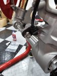
Front mudguard fitted. Wheel speed sensor and hydraulic lines need careful routeing, as per the workshop manual, including spacing and orientation of the "fast clips" as Ducati term them.
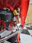
Front calipers, DP air ducts and Stahlbus bleeder banjo bolts and dust caps fitted. Hydraulic lines torqued to 24.5Nm. Calipers will be torqued once the front wheel is fitted.
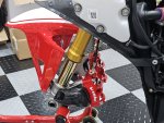
Gear position sensor cooling duct fitted. I had to order a couple of grommets for this part, which fit over the two metal studs on the sensor as they had split.
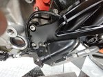
Before fitting the LH rearset, I added this extra titanium part from MotoCorse.
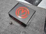
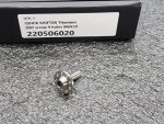
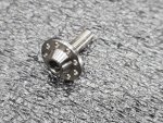
Dab of Loctite 243 and torqued to 10Nm, remembering to add the nylon washer behind the bolt head
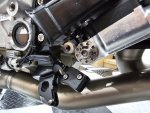
LH rearset fitted, using Pro Bolt M8 x 20mm tapered socket cap bolts, torqued to 25Nm. A lot may wonder why I chose not to keep the Rizoma rearsets that come as standard with this bike, simple answer being I don't much like them, though they are nicely machined and a quality part.
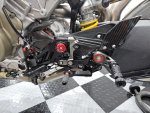

Front mudguard fitted. Wheel speed sensor and hydraulic lines need careful routeing, as per the workshop manual, including spacing and orientation of the "fast clips" as Ducati term them.

Front calipers, DP air ducts and Stahlbus bleeder banjo bolts and dust caps fitted. Hydraulic lines torqued to 24.5Nm. Calipers will be torqued once the front wheel is fitted.

Gear position sensor cooling duct fitted. I had to order a couple of grommets for this part, which fit over the two metal studs on the sensor as they had split.

Before fitting the LH rearset, I added this extra titanium part from MotoCorse.


Dab of Loctite 243 and torqued to 10Nm, remembering to add the nylon washer behind the bolt head

LH rearset fitted, using Pro Bolt M8 x 20mm tapered socket cap bolts, torqued to 25Nm. A lot may wonder why I chose not to keep the Rizoma rearsets that come as standard with this bike, simple answer being I don't much like them, though they are nicely machined and a quality part.

topolino
Well-known member
Before fitting the RHS rearset, as the original rearsets were Rizomas, they use a different actuating rod, spring, brake switch adjustable bolt, locking nuts
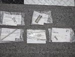
and pin to the stock rearsets, which won't work with the Gilles. In anticipation of this issue I pre-ordered these stock parts that will allow me to build up the RHS assembly.
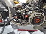
As mentioned earlier, I had to dispense with both the billet reservoir and reservoir delete fairlead cover, as there is no clearance between the collector pipe and reservoir in this position, which if fitted, the heat from the exhaust would probably end up cooking the hydraulic fluid. I may look at other options but for now I will leave the stock setup.
There is a LOT going on here, including having to route and cable manage the two rear lambda sensors, rear wheel speed sensor, rear brake line, brake reservoir feed pipe and brake light switch, so that they don't foul on anything and as best as possible keep them away from contact with the exhaust. Hydraulic line to the rear master cylinder was secured using a Racebolt stainless banjo bolt torqued to 24.5Nm You might also spot the Pro Bolt M6 x 10mm reservoir bolt. As this is going into a brass threaded insert I opted to use 5Nm as a safe bet, since there is no figure given for it in the manual.
You will also obviously see the collector pipes and the main rear upswept pipe that has an enormous diameter, to which will attach the loop pipe and silencers. More on those later. This system is contortuous to put it mildly and needs a lot of adjustment to get it to fit right with still more tweaks to do once the rear sections are fitted, the rear subframe is back on and the support bracket is in place.
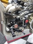
RHS rear set secured using 2 x Pro Bolt M8 x 20mm bolts torqued to 25Nm
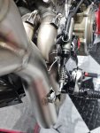
As can be seen, there is not much room to play with! Spriing has about 5mm of clearance to the collector pipe, so all good.
Just waiting on one more small part to complete the RHS lower wiring, with just the front and rear loom branches to wire in, but before that I need to mount both front and rear subframes. Speaking of which, I decided to make a small change to rear subframe, the reason for which will become apparent once the frame is fitted back onto the bike.
Before that though I took the opportunity to fit the rear hugger and swing cover back on, as access to the bolts is easier without the subframe in the way. All retaining bolts torqued to 5Nm and a dab of Loctite 243. Don't be alarmed by the "Easy Rider" appearance of the exhaust at this stage. It will make a lot more sense when you see the rest of it in place.
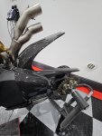
Now back to the subframe. A little masking off required.
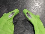
Then two coats of Ultra High Temp paint later and they look like this.
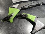
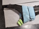
Once dry and the masking tape removed, I could apply some Parabond to the heat reflective foil area on both frame members, before securing the Lieb Speed carbon covers in place with zip ties as the bonding agent fully cures (in around 24 hours). The covers are not only secured to the subframe by bonding agent but in fact by four other bolts on each side. The reason for the bonding agent is to ensure the central area of the cover is as close a fit to the underlying subframe and cannot lift away from the surface.
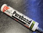
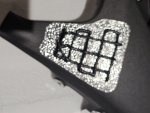
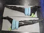
The reason for the paint application will become clear later. That's all for tonight. Early shift at work in the morning, so I will try and post some more updates, later this week
and pin to the stock rearsets, which won't work with the Gilles. In anticipation of this issue I pre-ordered these stock parts that will allow me to build up the RHS assembly.

As mentioned earlier, I had to dispense with both the billet reservoir and reservoir delete fairlead cover, as there is no clearance between the collector pipe and reservoir in this position, which if fitted, the heat from the exhaust would probably end up cooking the hydraulic fluid. I may look at other options but for now I will leave the stock setup.
There is a LOT going on here, including having to route and cable manage the two rear lambda sensors, rear wheel speed sensor, rear brake line, brake reservoir feed pipe and brake light switch, so that they don't foul on anything and as best as possible keep them away from contact with the exhaust. Hydraulic line to the rear master cylinder was secured using a Racebolt stainless banjo bolt torqued to 24.5Nm You might also spot the Pro Bolt M6 x 10mm reservoir bolt. As this is going into a brass threaded insert I opted to use 5Nm as a safe bet, since there is no figure given for it in the manual.
You will also obviously see the collector pipes and the main rear upswept pipe that has an enormous diameter, to which will attach the loop pipe and silencers. More on those later. This system is contortuous to put it mildly and needs a lot of adjustment to get it to fit right with still more tweaks to do once the rear sections are fitted, the rear subframe is back on and the support bracket is in place.

RHS rear set secured using 2 x Pro Bolt M8 x 20mm bolts torqued to 25Nm

As can be seen, there is not much room to play with! Spriing has about 5mm of clearance to the collector pipe, so all good.

Just waiting on one more small part to complete the RHS lower wiring, with just the front and rear loom branches to wire in, but before that I need to mount both front and rear subframes. Speaking of which, I decided to make a small change to rear subframe, the reason for which will become apparent once the frame is fitted back onto the bike.
Before that though I took the opportunity to fit the rear hugger and swing cover back on, as access to the bolts is easier without the subframe in the way. All retaining bolts torqued to 5Nm and a dab of Loctite 243. Don't be alarmed by the "Easy Rider" appearance of the exhaust at this stage. It will make a lot more sense when you see the rest of it in place.

Now back to the subframe. A little masking off required.

Then two coats of Ultra High Temp paint later and they look like this.

Once dry and the masking tape removed, I could apply some Parabond to the heat reflective foil area on both frame members, before securing the Lieb Speed carbon covers in place with zip ties as the bonding agent fully cures (in around 24 hours). The covers are not only secured to the subframe by bonding agent but in fact by four other bolts on each side. The reason for the bonding agent is to ensure the central area of the cover is as close a fit to the underlying subframe and cannot lift away from the surface.


The reason for the paint application will become clear later. That's all for tonight. Early shift at work in the morning, so I will try and post some more updates, later this week

topolino
Well-known member
OK so after much fenagling, I managed to assemble the rear subframe, complicated by the fact it needs to incorporate the Termignoni undertray, which at first appeared to not fit particularly well but after some deliberation and adjustments, it all worked out OK.
Here's the cross frame member that I had cerakoted "Glacier Black". I didn't like the stock zinc coated finish so that had to go.
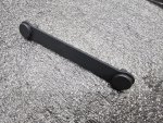
With that in place and connecting the two halves of the subframe together, I could begin to assemble the undertray to the frame members. I had it clear coated to match the rest of the carbon parts on the bike. I am not sure why they placed the large hole where it is (into which you are meant to insert the supplied grommet), as it is in totally the wrong place for the DES wiring, so I will buy a blanking grommet instead to seal it up. As it happens they have moulded an aperture into the side of the undertray which is where the DES wiring will logically be routed. Termignoni supply metal spacers for the four main fixing points and stainless button head bolts. In addition you have to reuse 2 OEM bolts that secure the front of the tray to the subframe.
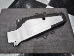
Here is the subframe fully assembled. All bolts torqued to 5Nm, since the stock figures, at least for the 4 main bolts, are for the passenger footpegs and do not need to be that tight, given they are only retaining a thin carbon panel. The same goes for the front two bolts. A dab of loctite on each and it's done.
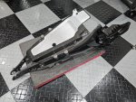
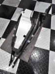
Next job was to fit the frame back on the bike. I used two new lower bolts and the top two are new MotoCorse ones, see later images. All four bolts torqued to 31Nm, which has changed from earlier models which used two different settings for upper and lower bolts.
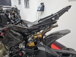
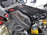
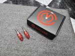
The Moto Corse bolt/frame plug is made up of three parts. I did have to open up the holes in the carbon fibre cover as they partially obscured the machined hole in the frame, which would have made fitting them impossible.
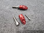
With the frame now secured to the bike, it was time to make a start on the rear wiring loom.
This is where the DES wiring is routed. I will come back to this later.
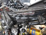
A view from inside. Cross member M8 stainless locking nuts, torqued to 22Nm
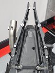
Here's the cross frame member that I had cerakoted "Glacier Black". I didn't like the stock zinc coated finish so that had to go.

With that in place and connecting the two halves of the subframe together, I could begin to assemble the undertray to the frame members. I had it clear coated to match the rest of the carbon parts on the bike. I am not sure why they placed the large hole where it is (into which you are meant to insert the supplied grommet), as it is in totally the wrong place for the DES wiring, so I will buy a blanking grommet instead to seal it up. As it happens they have moulded an aperture into the side of the undertray which is where the DES wiring will logically be routed. Termignoni supply metal spacers for the four main fixing points and stainless button head bolts. In addition you have to reuse 2 OEM bolts that secure the front of the tray to the subframe.

Here is the subframe fully assembled. All bolts torqued to 5Nm, since the stock figures, at least for the 4 main bolts, are for the passenger footpegs and do not need to be that tight, given they are only retaining a thin carbon panel. The same goes for the front two bolts. A dab of loctite on each and it's done.


Next job was to fit the frame back on the bike. I used two new lower bolts and the top two are new MotoCorse ones, see later images. All four bolts torqued to 31Nm, which has changed from earlier models which used two different settings for upper and lower bolts.


The Moto Corse bolt/frame plug is made up of three parts. I did have to open up the holes in the carbon fibre cover as they partially obscured the machined hole in the frame, which would have made fitting them impossible.


With the frame now secured to the bike, it was time to make a start on the rear wiring loom.
This is where the DES wiring is routed. I will come back to this later.

A view from inside. Cross member M8 stainless locking nuts, torqued to 22Nm


