I researched PDMs about 5 years ago while planning to buy a new sports tourer. Had visions of extra lights, cameras, various electrical gadgets. But the V4 came along and diverted my attention away from all of that.
But a sportbike doesn't typically carry a swag of accessories so initially I was going to use a couple of relays to power my phone and heated vest. However it quickly became clear that space was at a premium, I would end up with a cable and relay rat nest and adding anything else in future would just be difficult. There's also the chance that a camera (or USB plug for one) and maybe heated grips (which are essential on premium German sportbikes but not even an option on Italian) could be a future project.
So I looked at PDMs again. Where I had pretty much decided upon - and was looking forward to tinkering with - a Rowe Electronics PDM50 (which, by the way, is totally excessive overkill, far and away beyond what I could ever need) technology had moved on and there was now a bluetooth version that utilised a smart phone for display and control. Perfect. A new gadget. Guys love gadgets. I'm a guy. (What? You were expecting a common sense decision?)
Advantages that I liked. The PDM is very compact (3" x 2" x 1"), isolates all accessories from the Canbus, provides ignition switched supply and selectable time delay on/off so nothing saps power while trying to start the bike. Each fuse is actually a circuit breaker and can easily be reset. And set-up/control is via my phone.
Concerns. It's very expensive even with the 20% off that I managed to find. And heat tolerance is not particularly good at max rated 80C. Location would be an issue.
Location is THE issue. None of the usual places - around the battery, under the seat, in the tail - are available. Simply not enough room. The one obvious and safe place is the nose. Plenty of room in the V4's nose but a bit of a job to get access if you need to. And I wanted to have visibility of the single LED that is on the unit. The LED assures you that all is working and it indicates when bluetooth pairing is open. So decided to try a risky location on the left flank behind, and hopefully far enough above, the radiator to catch a flow of cool air from between the forks. On the 2020 this location is immediately below the black metal grill that punctuates the left fairing upper. So allows more ventilation as well as visibility of that LED.
As you'll see later I have made an attempt to insulate the module and all cables from radiant heat. I've been running it without issue now for a good month. But summer is a-comin'. Time will tell.
Fitting the unit. This was all trial and error, guessing how much room was available (it's very difficult to measure), looking around the garage for ideas on how to mount it (ah, some roofing steel, already colour bonded, that'll do), and nipping down to the local bolt specialist (we have one?!) before he shuts.
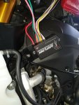
Amplink is mounted on an offcut from a sheet of Colourbond roof capping which I sprayed black. Single bolt on the left connects it to the bike - replaced existing fairing stud (not used on the 2020), which also holds the radiator frame, with a stainless bolt. The tin is easily bent and twisted into a complex shape so it sits parallel to a fairly complex part of the frame.
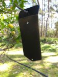
I created an air gap between the module and the tin piece using a pair of stainless nuts as spacers. Then a 1/4" gap between the tin and the bike frame is maintained by some spacers - here I used felt furniture feet but later stacked up pieces of adhesive-backed foil insulation. On the right you can see my earthing cable secured under a fairing stud - I covered all cables in black webbing heat shield and bound each end in heat-shrink. All accessories terminate on this earth lead keeping the battery uncluttered. (It has a ring terminal with bolt and nut at the other end so each accessory's -ve lead is finished with a ring terminal that simply slips over the bolt.)
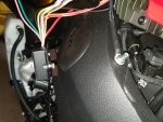
At this point I made sure the fairing would go back on! Then sourced some adhesive-backed reflective heat shielding. Honestly looked all over the place on the internet for this. It's expensive and the price is doubled when you add freight. Then all of a sudden it occurred to me to check out the local Auto parts shop. Bingo! And it's g-g-g-gold!
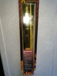
Dismantled the module from the tin piece. Cut some insulation to shape and made sure the Amplink was completely shielded. (Doesn't seem to impede the Bluetooth too much.) Organised the various cables into groups and gave them some black heat shield webbing (which I sourced from a local Jaycar electronics shop) . Paid particular attention to where cables enter the Amplink, double wrapping here.
The gold braid (basalt, extra high temp - but...er...I just like the look) going off to the rear is my battery maintenance connection. The +ve supply comes directly from the Amplink's always-on 7th circuit. Although shown here earthed to the frame stud, I later used this same stud to anchor the Amplink's common earth and the two together raised the stud too high, distorting the fairing. So instead I ultimately extended this charge cable earth all the way to the Amplink's common earth (which is tucked-in in front of the battery). This photo was taken before I installed the Common.
The thick loom curling off to the left is spare circuits tucked up and out of harm's (heat's) way. There are two black looms running up to the battery area. One has the +ve and -ve supply going to the battery as well as the ignition "switch" lead which terminates on a piggy back fuse (left side, position number 5, 5A Accessories); the other contains the two power circuits for my phone and heated clothing.
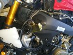
I did replace the felt pads with a spacer that I made by stacking about 10 layers of heat shield. Was petrified that the felt would catch fire.
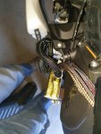
All terminations onto the Amplink pigtails and Common earth sit in the space in front of the battery. You can see the Common earth at left (the shiny steel bolt) - I added a piece of clear vinyl tube over the top for safety. Also added a fuse to the Amplink +ve supply (currently 30A as that's all I could buy on the day, it can take 60A but I'm only drawing 7A max and feeding less than 1A, max 5A, from the charger).
On the right you can just see a tiny speck of red wire where the ignition feed taps in. I used a mini-fuse piggy back which was a neat solution that I liked because it is easily unplugged if I want to remove the Amplink. A posi-tap would be equally good joining to the same wire. My wife's Dymo labeller came in handy.
 ì
ì
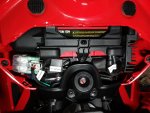
I could have saved a lot more space in this very small battery void by cutting wires to length. I might do that after the who shebang has proved it can survive the heat of summer.
Oh, and the gold cable sheath - I used this down the left side to run my battery charge cable to the tail. And same on the right side to run cable for heated clothing. Here's my battery charge socket...I stuck with SAE connectors even though I have a CTEK charger because they are the most common and the most rugged. I used an Optimate O-11 (short) cable for it's excellent socket and weatherproof housing, cut the ring terminals off and soldered to a length of 15A cable which I ran to the front. A bit of 3mm spiral wrap adds some physical protection for the short Optimate section and is a nicer look than a plain twin cable.
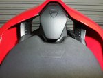
This is the right side where I ran the cable for my heated vest. I hardly ever need this but when I do it's brilliant. It runs under the seat and the socket pokes out in that gap between seat and tank. (For most of the year I'll leave the socket tucked under the seat.) Some clear vinyl wrap protects the tank. The actual cable is an Optimate O-21 heavy duty rig with 20" of 18AWG cable and a nice rugged socket. The rubber weather plug is a bit of a pain as it likes to fall out but the pre-fab cable was just the right length - I cut off the ring terminals and used a supplied posi-join to link it to the Amplink lead.

I just like the gold... ...
...
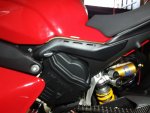
I should probably do another post to cover the SP-Connect phone mount. Suffice to say it too connects to the Amplink within that space behind in front of the battery. I added black cable sheath, not for heat shielding this time, just for looks.
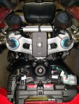
Speaking of the phone, that is how the Amplink is set-up and monitored. You download an app from Rowe Electronics onto your phone, turn the ignition on to spark bluetooth pairing into life on the Amplink - the little green LED flashes - cross your fingers and make a wish. This should establish connection between module and phone app.
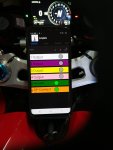
The app is a bit agricultural in looks but works well. You can see I've used circuits 5 and 6. There are a couple of screens where for each of 6 circuits you choose fuse size, any of 3 switches you want to include in each circuit (both the physical type and/or ignition), and set the delay length for both power on and off (ie a delay after ignition is turned on or off). Mine are both set to a 30 second delay before powering on so that maximum battery power is available to the starter motor. You can watch them spring to life on the app. If desired I could allow my heated vest to keep operating for a while after killing the ignition - but I don't. There's a 7th always-on circuit and that is where I have my battery charger cable connected.
That's it. End of story...almost. Just need to see how it goes during hot weather. So hopefully in maybe 6 months I'll make a post to confirm it's all still going well. Either that or a very expensive piece of toast.
But a sportbike doesn't typically carry a swag of accessories so initially I was going to use a couple of relays to power my phone and heated vest. However it quickly became clear that space was at a premium, I would end up with a cable and relay rat nest and adding anything else in future would just be difficult. There's also the chance that a camera (or USB plug for one) and maybe heated grips (which are essential on premium German sportbikes but not even an option on Italian) could be a future project.
So I looked at PDMs again. Where I had pretty much decided upon - and was looking forward to tinkering with - a Rowe Electronics PDM50 (which, by the way, is totally excessive overkill, far and away beyond what I could ever need) technology had moved on and there was now a bluetooth version that utilised a smart phone for display and control. Perfect. A new gadget. Guys love gadgets. I'm a guy. (What? You were expecting a common sense decision?)
Advantages that I liked. The PDM is very compact (3" x 2" x 1"), isolates all accessories from the Canbus, provides ignition switched supply and selectable time delay on/off so nothing saps power while trying to start the bike. Each fuse is actually a circuit breaker and can easily be reset. And set-up/control is via my phone.
Concerns. It's very expensive even with the 20% off that I managed to find. And heat tolerance is not particularly good at max rated 80C. Location would be an issue.
Location is THE issue. None of the usual places - around the battery, under the seat, in the tail - are available. Simply not enough room. The one obvious and safe place is the nose. Plenty of room in the V4's nose but a bit of a job to get access if you need to. And I wanted to have visibility of the single LED that is on the unit. The LED assures you that all is working and it indicates when bluetooth pairing is open. So decided to try a risky location on the left flank behind, and hopefully far enough above, the radiator to catch a flow of cool air from between the forks. On the 2020 this location is immediately below the black metal grill that punctuates the left fairing upper. So allows more ventilation as well as visibility of that LED.
As you'll see later I have made an attempt to insulate the module and all cables from radiant heat. I've been running it without issue now for a good month. But summer is a-comin'. Time will tell.
Fitting the unit. This was all trial and error, guessing how much room was available (it's very difficult to measure), looking around the garage for ideas on how to mount it (ah, some roofing steel, already colour bonded, that'll do), and nipping down to the local bolt specialist (we have one?!) before he shuts.

Amplink is mounted on an offcut from a sheet of Colourbond roof capping which I sprayed black. Single bolt on the left connects it to the bike - replaced existing fairing stud (not used on the 2020), which also holds the radiator frame, with a stainless bolt. The tin is easily bent and twisted into a complex shape so it sits parallel to a fairly complex part of the frame.

I created an air gap between the module and the tin piece using a pair of stainless nuts as spacers. Then a 1/4" gap between the tin and the bike frame is maintained by some spacers - here I used felt furniture feet but later stacked up pieces of adhesive-backed foil insulation. On the right you can see my earthing cable secured under a fairing stud - I covered all cables in black webbing heat shield and bound each end in heat-shrink. All accessories terminate on this earth lead keeping the battery uncluttered. (It has a ring terminal with bolt and nut at the other end so each accessory's -ve lead is finished with a ring terminal that simply slips over the bolt.)

At this point I made sure the fairing would go back on! Then sourced some adhesive-backed reflective heat shielding. Honestly looked all over the place on the internet for this. It's expensive and the price is doubled when you add freight. Then all of a sudden it occurred to me to check out the local Auto parts shop. Bingo! And it's g-g-g-gold!

Dismantled the module from the tin piece. Cut some insulation to shape and made sure the Amplink was completely shielded. (Doesn't seem to impede the Bluetooth too much.) Organised the various cables into groups and gave them some black heat shield webbing (which I sourced from a local Jaycar electronics shop) . Paid particular attention to where cables enter the Amplink, double wrapping here.
The gold braid (basalt, extra high temp - but...er...I just like the look) going off to the rear is my battery maintenance connection. The +ve supply comes directly from the Amplink's always-on 7th circuit. Although shown here earthed to the frame stud, I later used this same stud to anchor the Amplink's common earth and the two together raised the stud too high, distorting the fairing. So instead I ultimately extended this charge cable earth all the way to the Amplink's common earth (which is tucked-in in front of the battery). This photo was taken before I installed the Common.
The thick loom curling off to the left is spare circuits tucked up and out of harm's (heat's) way. There are two black looms running up to the battery area. One has the +ve and -ve supply going to the battery as well as the ignition "switch" lead which terminates on a piggy back fuse (left side, position number 5, 5A Accessories); the other contains the two power circuits for my phone and heated clothing.

I did replace the felt pads with a spacer that I made by stacking about 10 layers of heat shield. Was petrified that the felt would catch fire.

All terminations onto the Amplink pigtails and Common earth sit in the space in front of the battery. You can see the Common earth at left (the shiny steel bolt) - I added a piece of clear vinyl tube over the top for safety. Also added a fuse to the Amplink +ve supply (currently 30A as that's all I could buy on the day, it can take 60A but I'm only drawing 7A max and feeding less than 1A, max 5A, from the charger).
On the right you can just see a tiny speck of red wire where the ignition feed taps in. I used a mini-fuse piggy back which was a neat solution that I liked because it is easily unplugged if I want to remove the Amplink. A posi-tap would be equally good joining to the same wire. My wife's Dymo labeller came in handy.
 ì
ìI could have saved a lot more space in this very small battery void by cutting wires to length. I might do that after the who shebang has proved it can survive the heat of summer.
Oh, and the gold cable sheath - I used this down the left side to run my battery charge cable to the tail. And same on the right side to run cable for heated clothing. Here's my battery charge socket...I stuck with SAE connectors even though I have a CTEK charger because they are the most common and the most rugged. I used an Optimate O-11 (short) cable for it's excellent socket and weatherproof housing, cut the ring terminals off and soldered to a length of 15A cable which I ran to the front. A bit of 3mm spiral wrap adds some physical protection for the short Optimate section and is a nicer look than a plain twin cable.

This is the right side where I ran the cable for my heated vest. I hardly ever need this but when I do it's brilliant. It runs under the seat and the socket pokes out in that gap between seat and tank. (For most of the year I'll leave the socket tucked under the seat.) Some clear vinyl wrap protects the tank. The actual cable is an Optimate O-21 heavy duty rig with 20" of 18AWG cable and a nice rugged socket. The rubber weather plug is a bit of a pain as it likes to fall out but the pre-fab cable was just the right length - I cut off the ring terminals and used a supplied posi-join to link it to the Amplink lead.

I just like the gold...

I should probably do another post to cover the SP-Connect phone mount. Suffice to say it too connects to the Amplink within that space behind in front of the battery. I added black cable sheath, not for heat shielding this time, just for looks.

Speaking of the phone, that is how the Amplink is set-up and monitored. You download an app from Rowe Electronics onto your phone, turn the ignition on to spark bluetooth pairing into life on the Amplink - the little green LED flashes - cross your fingers and make a wish. This should establish connection between module and phone app.
The app is a bit agricultural in looks but works well. You can see I've used circuits 5 and 6. There are a couple of screens where for each of 6 circuits you choose fuse size, any of 3 switches you want to include in each circuit (both the physical type and/or ignition), and set the delay length for both power on and off (ie a delay after ignition is turned on or off). Mine are both set to a 30 second delay before powering on so that maximum battery power is available to the starter motor. You can watch them spring to life on the app. If desired I could allow my heated vest to keep operating for a while after killing the ignition - but I don't. There's a 7th always-on circuit and that is where I have my battery charger cable connected.

That's it. End of story...almost. Just need to see how it goes during hot weather. So hopefully in maybe 6 months I'll make a post to confirm it's all still going well. Either that or a very expensive piece of toast.
Last edited:
